A linear direct-acting electromagnet

An electromagnet, linear technology, applied in the direction of electromagnets, electromagnets, circuits, etc. with armatures, can solve the problems of entering impurities and moisture, accelerating the speed of corrosion and rusting of moving parts, and the failure of electromagnets to work normally, and achieves increased The effect of the ability to lock

Pending Publication Date: 2018-12-18
苏州耀德科电磁技术有限公司
View PDF0 Cites 0 Cited by
  • Summary
  • Abstract
  • Description
  • Claims
  • Application Information

AI Technical Summary

Problems solved by technology

The electromagnets on the market usually include a bracket, a coil and a telescopic rod. The bracket is fixedly connected to the coil. There are through holes on the bracket. The telescopic rod includes a push rod and a top sleeve. The setting of the through hole makes it easy for the electromagnet to enter impurities and water from the through hole during use. The impurities include oil stains, dust, etc. The water will accelerate the corrosion and rust of the moving parts, and the impurities and rust will affect the smooth movement of the moving parts. Ultimately, the electromagnet will not work properly, requiring disassembly and replacement, wasting manpower and resources

Method used


Image

  • A linear direct-acting electromagnet
  • A linear direct-acting electromagnet

Examples


Embodiment Construction

[0010] The preferred embodiments of the present invention will be described in detail below in conjunction with the accompanying drawings, so that the advantages and features of the present invention can be more easily understood by those skilled in the art, so as to define the protection scope of the present invention more clearly.

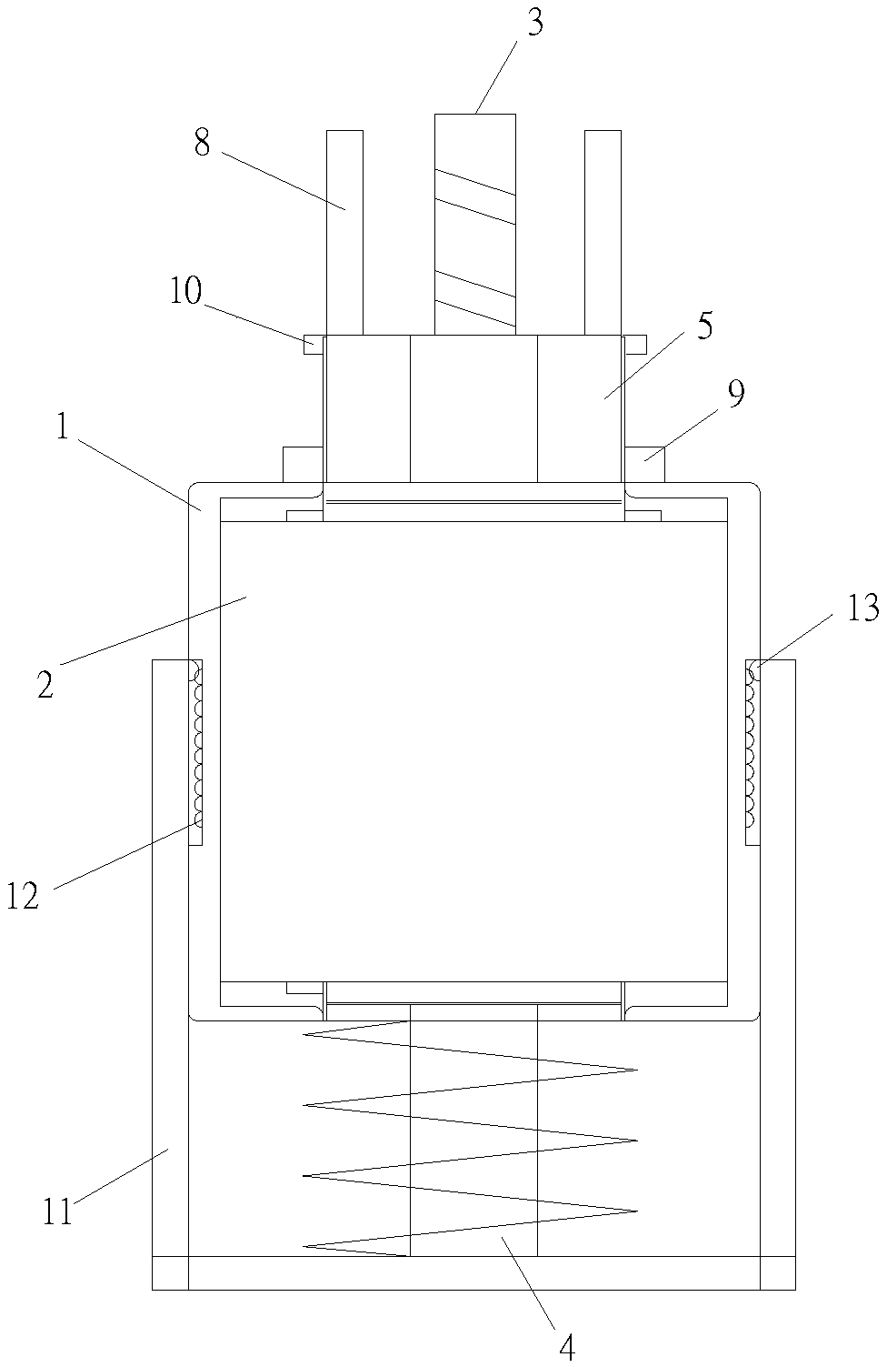
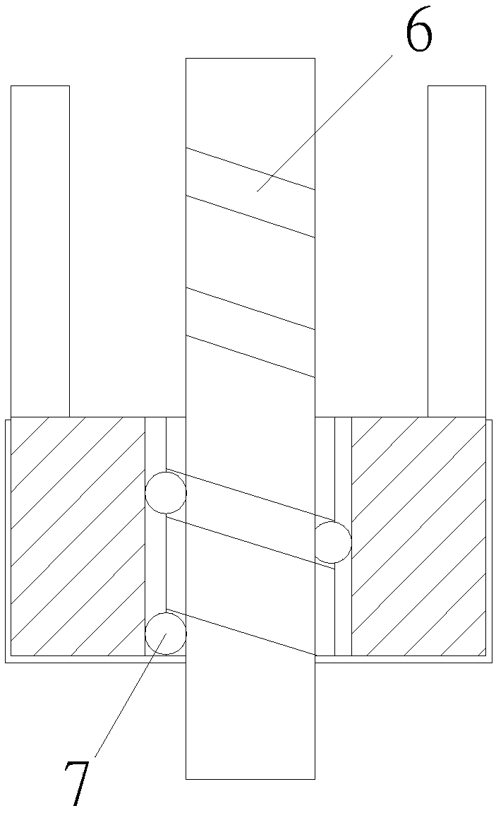
[0011] Please refer to the attached figure 1 and 2 , the embodiment of the present invention includes:

[0012] A linear direct-moving electromagnet, including an outer frame 1, a static iron core 2 and a moving iron core, the static iron core 2 is coaxially installed in the outer frame 1, and coils are wound on the static iron core 2; the moving iron core is coaxially matched In the static iron core 2; the shaft core of the moving iron core is provided with a central rod that runs through the outer frame; one end of the central rod is a telescopic working end 3, and the other end is a limit end 4 that pushes through and limits the space. A ret...


PUM


Abstract

A linear direct-moving electromagnet comprises an outer frame, a static iron core and a moving iron core, wherein the static iron core is coaxially arrange in the outer frame and a coil is wound on the static iron core; the moving iron core is coaxially fitted in the static iron core; the shaft core of the movable iron core is provided with a central rod penetrating the outer frame; one end of thecenter rod is a telescopic working end, and the other end thereof is a limit end for pushing the limit position; a rotary disk is sleeved on the working end; the rotary disk is movably connected withthe outer frame; a spiral inner ball groove is arranged in the shaft hole of the rotary disk, and the corresponding outer ball groove is arranged on the working end; a stainless steel ball is arranged between the inner ball groove and the outer ball groove; the rotary disk is provided with a lock head parallel to the working end; and the movable iron core performs expansion and contraction to drive the rotary disk to realize autorotation, and the lock head rotates around the working end. A locking structure capable of autorotation with the expansion and contraction of the push rod is added, and the locking structure is used for fitting in the specific locking structure, so that the locking ability can be increased, and the push rod can be protected from external force impact.

Description

technical field [0001] The invention relates to the field of electromagnet structure, in particular to a linear linear motion electromagnet. Background technique [0002] An electromagnet is a device that generates electromagnetism when energized. After inserting an iron core inside the coil, the iron core is magnetized by the magnetic field of the coil. The electromagnets on the market usually include a bracket, a coil and a telescopic rod. The bracket is fixedly connected to the coil. There are through holes on the bracket. The telescopic rod includes a push rod and a top sleeve. The setting of the through hole makes it easy for the electromagnet to enter impurities and water from the through hole during use. The impurities include oil stains, dust, etc. The water will accelerate the corrosion and rust of the moving parts. The impurities and rust will affect the smooth movement of the moving parts. Ultimately, the electromagnet cannot work normally, so it needs to be dism...

Claims


Application Information

Patent Timeline
IPC IPC(8): H01F7/08H01F7/16E05B47/02
CPCH01F7/08H01F7/1607E05B47/0002E05B47/023
Inventor 黄耀兵
Owner 苏州耀德科电磁技术有限公司
Why Eureka
Try Eureka