
Groove avoiding method for two-dimensional lidar patrol robot

A two-dimensional laser radar and inspection robot technology, applied in the field of robotics, can solve problems such as inability to obtain groove information, inability to operate safely, and inability to obtain groove data

Inactive Publication Date: 2018-12-18
成都交大光芒科技股份有限公司
View PDF5 Cites 1 Cited by
  • Summary
  • Abstract
  • Description
  • Claims
  • Application Information

AI Technical Summary

Problems solved by technology

In the automatic inspection mode, the movement trajectory of the inspection robot is limited through the deployment of engineers, and the inspection robot can automatically avoid obstacles and grooves; in the manual operation mode, the engineers can manually operate the inspection robot. Avoid obstacles and grooves; switch from the automatic inspection mode to the manual operation mode, and manually operate the inspection robot to avoid obstacles and grooves; but if the manual operation mode switches to the automatic inspection mode, after the manual operation is over, the inspection robot may It is not at the position defined by the network structure diagram. Since the inspection robot uses a two-dimensional laser radar sensor, it cannot obtain the information of the groove. The path automatically planned by the inspection robot to return to the position defined by the network structure diagram may pass through the groove. If you follow this path, you will fall into the groove
[0005] At present, the common two-dimensional laser radar inspection robot generally uses the SLAM algorithm to construct the planar electronic map. The scanned planar electronic map contains obstacle information, but because the two-dimensional laser radar is used, the groove cannot be identified
[0006] In the prior art, the 2D lidar intelligent robot mostly adopts the path planning scheme built in the robot operating system ROS. Due to the use of the 2D lidar, it is limited to be used for the robot to navigate on the plane, but in some In the case of grooves, such as power substations, the scheme regards the groove as a safe area because it cannot obtain the data of the groove, which may cause the inspection robot to fall during the navigation process.
[0007] Among the existing robot products that use two-dimensional laser radar for navigation, because the two-dimensional laser radar only scans the horizontal plane, it scans obstacles on the horizontal plane; It is suitable for path planning when the road surface is flat. During the inspection of power substations, due to the presence of grooves (such as oil guide grooves) on site, when the manual operation mode is switched to the automatic operation mode, the path planning cannot obtain the information of the oil guide grooves and cannot be avoided. , resulting in the possibility of falling into the groove during exercise, making it impossible to operate safely

Method used


Image

  • Groove avoiding method for two-dimensional lidar patrol robot
  • Groove avoiding method for two-dimensional lidar patrol robot
  • Groove avoiding method for two-dimensional lidar patrol robot

Examples


Embodiment 1

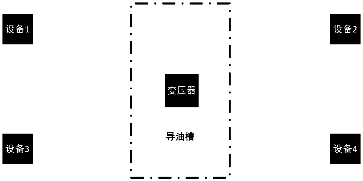
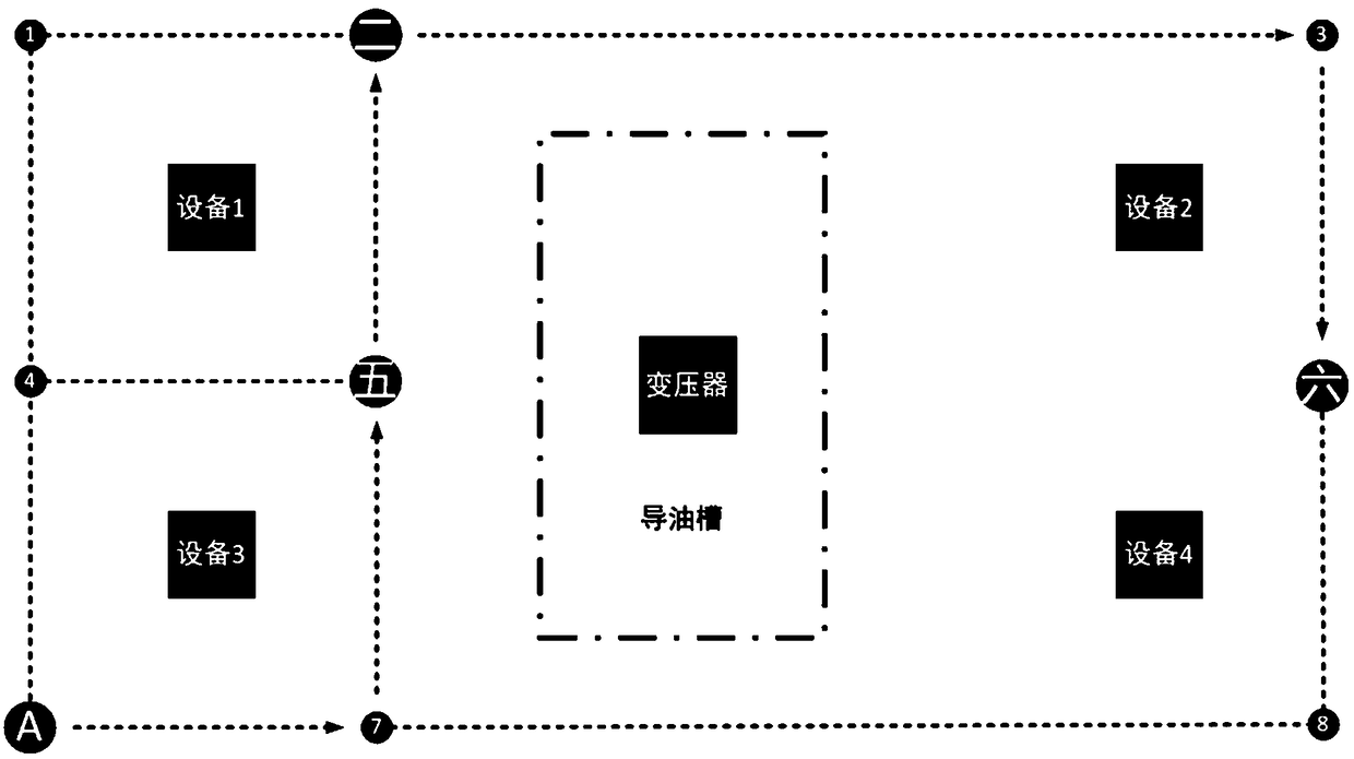
[0034] The present invention proposes a method for a two-dimensional laser radar inspection robot to avoid the groove, which realizes that when the inspection robot switches from the manual operation mode to the automatic inspection mode, it can smoothly return to the position defined by the network structure diagram, thereby continuing the inspection robot Automatic inspection work, such as figure 1 As shown, the following setting method is adopted in particular: In the automatic mode, the inspection robot merges the groove electronic map into the electronic map scanned by the inspection robot through the SLAM algorithm before path planning, and then performs path planning.

[0035] As a preferred design solution, when the manual mode is converted to the automatic mode, in the automatic mode, the inspection robot merges the groove electronic map into the electronic map scanned by the inspection robot through the SLAM algorithm before path planning, and then Carry out path plan...

Embodiment 2

[0037] This embodiment is further optimized on the basis of the above-mentioned embodiments. In order to better realize the present invention, the following setting method is adopted in particular: the electronic map of the groove is added on the input side of the path planning module, as a preferred In the design scheme, an electronic map of grooves is added on the input side of the path planning module, so that the purpose of reducing the amount of computation in the path planning and screening process can be achieved.

Embodiment 3

[0039] This embodiment is further optimized on the basis of any of the above-mentioned embodiments. Further, in order to better realize the present invention, the following configuration method is adopted in particular: the method includes the following specific steps:

[0040] 1) The inspection robot scans the electronic map through the SLAM algorithm, SLAM algorithm, simultaneous localization and mapping (SLAM) real-time positioning and map construction algorithm;

[0041] 2) Load the groove electronic map in the electronic map obtained in step 1); when loading the groove electronic map, use robot positioning + manual collection to form an xml file as the groove electronic map;

[0042] 3) Engineers lay out the network structure diagram on the basis of the electronic map formed in step 2; when laying out the network structure diagram, use robot positioning + manual collection, and then form it by manual editing;

[0043] 4) The inspection robot performs path planning in the ...


PUM


Abstract

The invention discloses a groove avoiding method for a two-dimensional lidar patrol robot. In the automatic mode, the patrol robot merges a groove electronic map into an electronic map scanned by thepatrol robot through the SLAM algorithm before performing path planning, the merged groove electronic map is placed on the input side of a path planning module, and then the path planning is performedto realize that the patrol robot can smoothly return to the position defined by a network structure diagram when the manual operation mode is switched to the automatic patrol mode, thereby continuingthe automatic patrol work of the patrol robot.

Description

technical field [0001] The invention relates to the fields of robot technology and the like, and specifically relates to a method for avoiding grooves of a two-dimensional laser radar inspection robot. Background technique [0002] The two-dimensional laser radar intelligent inspection robot in the railway substation (referred to as the inspection robot) is deployed in the railway substation, and plans the optimal inspection path according to the specified inspection task list (i.e., the list of task points). On the way forward, implement high-precision imaging detection on the instruments and components of railway substations. On the basis of automatic identification and analysis of the detection data, maintenance suggestions are formed to guide the elimination of hidden dangers of railway substation failures. [0003] In the automatic inspection mode, the inspection robot needs to take clear images of transformers, oil level gauges, insulators and other devices at a specif...

Claims


Application Information

Patent Timeline
Patent Type & Authority Applications(China)
IPC IPC(8): G01S17/93
CPCG01S17/931
Inventor 张春阳刘军陈奇志王倩
Owner 成都交大光芒科技股份有限公司
Learn More