
Three-axis inertial stabilized platform

A three-axis inertial and stable platform technology, applied in directions such as navigation through speed/acceleration measurement, can solve problems such as shooting accuracy interference, and achieve the effects of easy installation and maintenance, smooth transmission, and high precision

Active Publication Date: 2021-02-12
CHANGCHUN INST OF OPTICS FINE MECHANICS & PHYSICS CHINESE ACAD OF SCI
View PDF12 Cites 0 Cited by
  • Summary
  • Abstract
  • Description
  • Claims
  • Application Information

AI Technical Summary

Problems solved by technology

[0004] The purpose of the present invention is to provide a three-axis inertial stabilization platform based on flexible cable transmission, which aims to solve the technical problem that the shooting accuracy is disturbed due to the time and space backlash of the rigid transmission platform when the spontaneous vibration, resonance and flight attitude of the aircraft change.

Method used


Image

  • Three-axis inertial stabilized platform
  • Three-axis inertial stabilized platform
  • Three-axis inertial stabilized platform

Examples


Embodiment 1

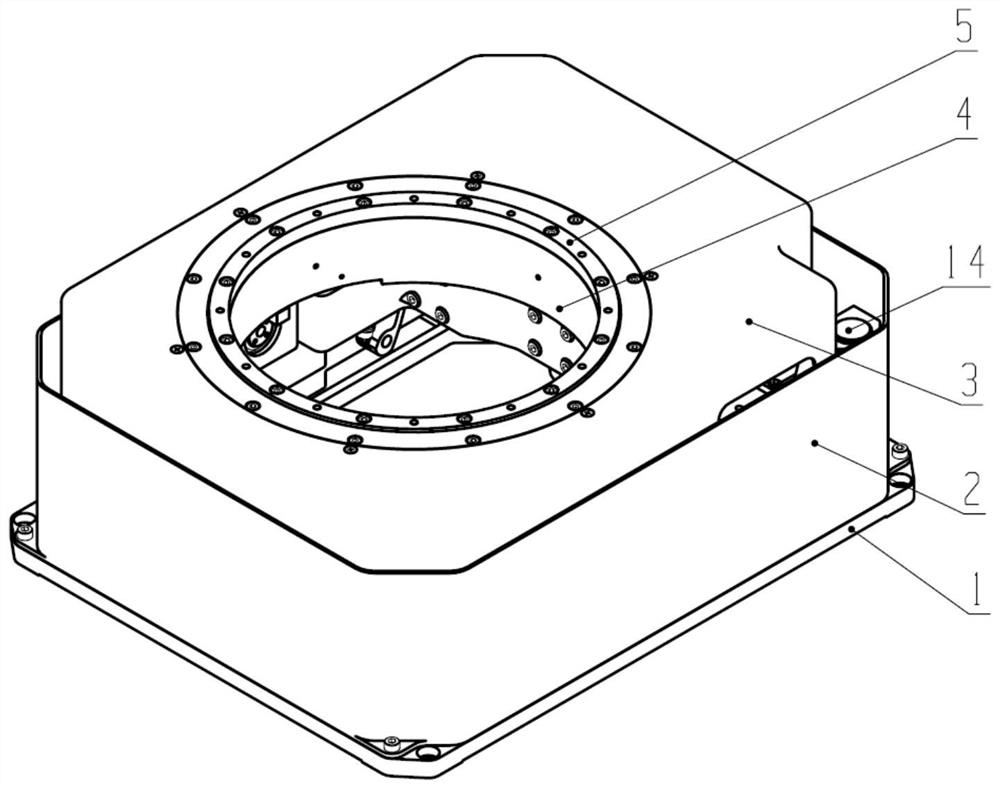
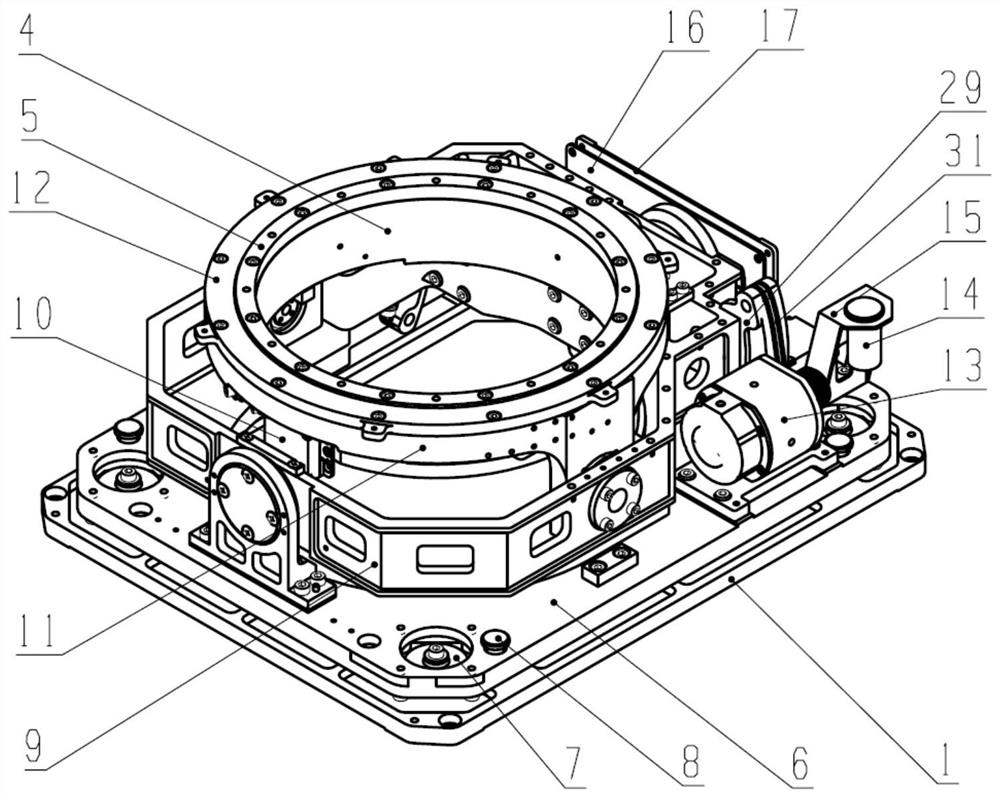
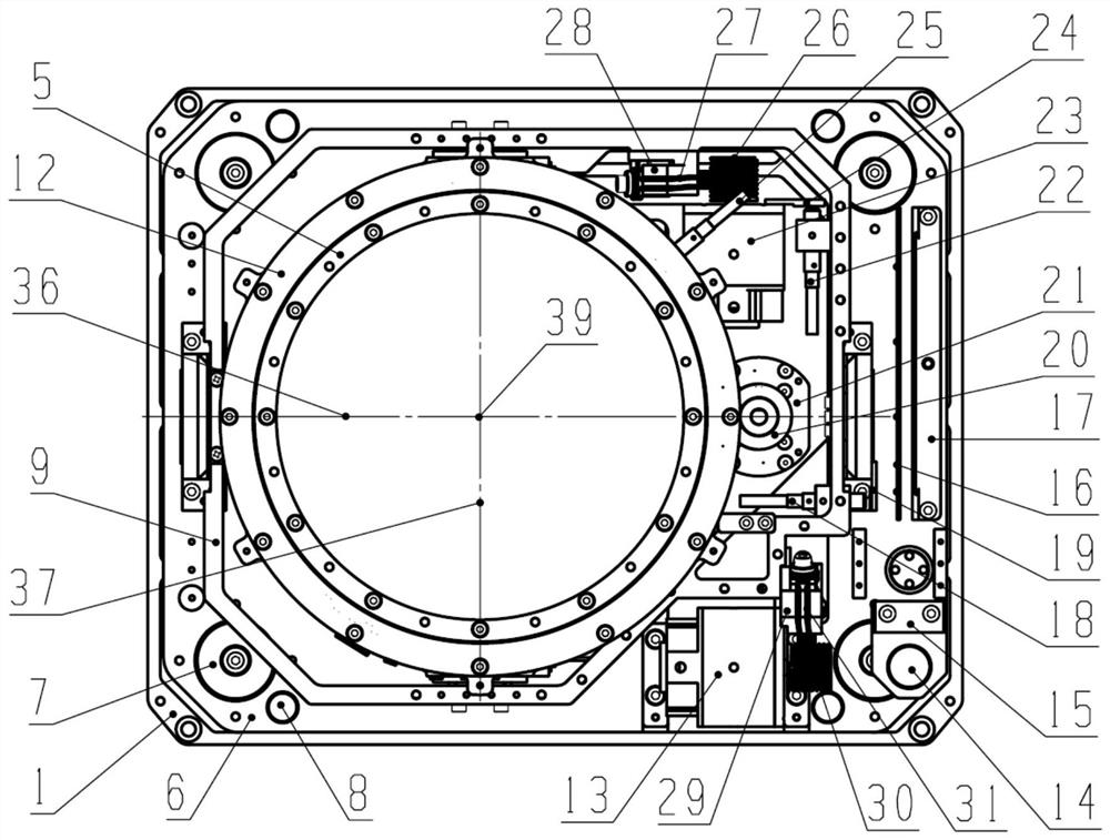
[0040] as attached Figure 1-5 As shown, the airborne light-duty three-axis inertial stabilization platform of the present invention includes a base 1, a side protection cover 2, an upper protection cover 3, an azimuth frame 4, an azimuth bearing inner pressure ring 5, a vibration damping seat 6, a shock absorber 7, an amplitude Limit mechanism 8, roll frame 9, three-axis inertial measurement unit 10, pitch frame 11, azimuth bearing outer pressure ring 12, roll drive assembly 13, electrical interface 14, electrical interface mounting base 15, controller 16, controller Mounting seat 17, roll zero sensor 18, roll zero detection object 19, azimuth drive threaded rod 20, azimuth drive assembly 21, pitch zero sensor 22, pitch drive assembly 23, pitch zero detection object 24, azimuth zero Position sensor 25, pitch drive threaded rod 26, pitch drive flexible cable 27, pitch drive passive wheel 28, roll drive passive wheel 29, roll drive threaded rod 30, roll drive flexible cable 31,...


PUM


Abstract

The present invention is applicable to the field of optoelectronic technology, and provides a three-axis inertial stable platform. The three-axis deceleration transmission system adopts a flexible cable transmission mode, and the rigidity of the flexible cable transmission can reach more than 10 times that of the same precision gear transmission or harmonic system. At the same time, it has the characteristics of high precision, low noise, smooth transmission, no lubrication, easy installation and maintenance, etc. The high rigidity and no backlash characteristics of the flexible cable precision transmission can ensure the fast dynamic response of the stable tracking servo system and improve the dynamic pointing accuracy of the platform.

Description

technical field [0001] The invention belongs to the field of optoelectronic technology, and in particular relates to a three-axis inertial stable platform. Background technique [0002] Aerial photography is an important tool for resource exploration, geological analysis, and military surveying and mapping. When installing a camera or video camera on an aircraft for remote sensing imaging, due to the influence of factors such as aircraft vibration and aircraft yaw, roll, and pitch movements, it will cause blurring, distortion, and rotation of the remote sensing image, seriously affecting the shooting effect, and even causing Images are difficult to use. In order to effectively compensate the impact of aircraft vibration and angular motion on camera equipment and improve the quality of aerial images, a platform that can accurately achieve three-axis gyro inertial stabilization is essential. [0003] In the prior art, such as U.S. Patent US5922039, Chinese Patents CN1305091A...

Claims


Application Information

Patent Timeline
Patent Type & Authority Patents(China)
IPC IPC(8): G01C21/18
CPCG01C21/18
Inventor 石磊王中石沈宏海许永森田大鹏
Owner CHANGCHUN INST OF OPTICS FINE MECHANICS & PHYSICS CHINESE ACAD OF SCI
Learn More