
Oil leaking detection and protection device for fan stationary blade adjustment hydraulic device

A technology for hydraulic devices and protection devices, which is applied to the components of pumping devices for elastic fluids, mechanical equipment, machines/engines, etc. Splash and waste, overall compactness, oil spill reduction effect

Active Publication Date: 2018-12-18
SHANGHAI MEISHAN IRON & STEEL CO LTD
View PDF4 Cites 3 Cited by
  • Summary
  • Abstract
  • Description
  • Claims
  • Application Information

AI Technical Summary

Problems solved by technology

Most of the vane adjustment technology uses a hydraulic transmission mechanism to drive the action of the vane. The biggest disadvantage of hydraulic drive is that it operates in a high temperature environment for a long time. The joint surface of the hydraulic oil return module and the gasket are aging, which can easily lead to leakage of hydraulic components. Oil will seriously affect the normal work of the hydraulic mechanism and bring great hidden dangers to the adjustment system
The stator blade adjustment system of the new No. 3 blast furnace blower in Meishan Iron and Steel Thermal Power Plant uses the power oil tank to supply high-pressure anti-fuel oil to the VOITH position valve, and the position valve acts as an actuator to drive the stator blade to adjust the air volume. In actual use of the system, there has been an oil leakage failure at the plane connection of the VOITH position valve hydraulically driven oil return module assembly. The increase in oil leakage directly leads to the failure of the hydraulic drive system to work normally. If it is shut down, it will seriously affect the normal operation of the blast furnace. Production

Method used


Image

  • Oil leaking detection and protection device for fan stationary blade adjustment hydraulic device
  • Oil leaking detection and protection device for fan stationary blade adjustment hydraulic device
  • Oil leaking detection and protection device for fan stationary blade adjustment hydraulic device

Examples


Embodiment 1

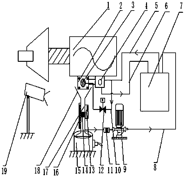
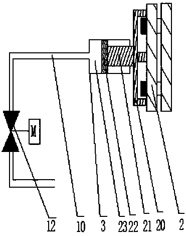
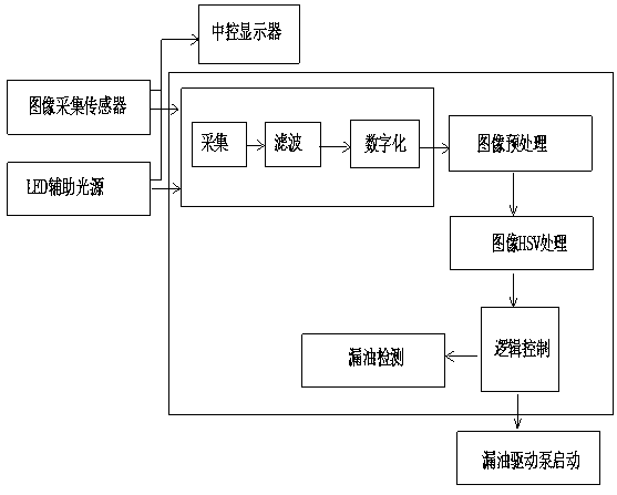
[0015] Embodiment 1: see figure 1 , figure 2 , an oil leakage detection and protection device for a fan stator blade adjustment hydraulic device, the protection device includes a steam blower unit 1, a hydraulic oil return module 2, a hydraulic locking device 3, a hydraulic drive valve 4, a drive valve oil inlet pipe 5, Drive valve oil return pipe 6, oil tank 7, oil leakage oil return pipe 8, oil leakage drive pump 9, locking device oil inlet pipe 10, filter device 11, electric control valve 12, magnetic induction switch 13, magnetic floating block 14, load cell 15 , a magnetic flap 16, an oil collection pipe 17, an oil collection tank 18 and an infrared image collector 19, a hydraulic oil return module 2 is provided below the steam-driven blower unit 1, and an oil collection tank is provided below the hydraulic oil return module 2 18. The oil collection tank 18 and the oil collection pipe 17 are extended and installed, and a load cell 15 is installed at the bottom of the oi...


PUM


Abstract

The invention relates to an oil leaking detection and protection device for a fan stationary blade adjustment hydraulic device. The automatic protection function can be achieved. According to the device, early warning can be realized during trace oil leakage, the oil leaking junction surface can be subjected to automatic on-line fastening through movements of an automatic hydraulic locking device,and thus the oil leaking amount can be reduced. When the oil leaking amount is increased and is beyond the limit, an oil leaking driving pump can be started by triggering of a magnetic induction switch to pump leaked oil back into an oil tank; and oil leaking points can be monitored in real time at the same time through the image detection, recognition, judgment and output technology. Meanwhile,the oil leaking amount is subjected to logical judgment output through the image recognition and judgment functions. The image recognition technology can further be interlocked with the oil leaking driving pump to act and serves as hot standby equipment when the magnetic induction switch breaks down. In this way, through the complete set of the device with the oil leaking detection, judgment and protection functions, normal work stability of a blast furnace blower set stationary blade adjusting system is guaranteed.

Description

technical field [0001] The invention relates to a detection device, in particular to an oil leakage detection and protection device for a hydraulic device for adjusting fan stator blades, and belongs to the technical field of electric instrument control. Background technique [0002] At present, the large-scale steam-driven blower units for blast furnace ironmaking all adopt the technology of adjustable vane to realize the adjustment of air volume to meet the production needs of blast furnace ironmaking. Most of the stator vane adjustment technology uses a hydraulic transmission mechanism to drive the action of the vane. The biggest disadvantage of hydraulic drive is that it operates in a high temperature environment for a long time. The joint surface of the hydraulic oil return module and the gasket are aging, which can easily lead to leakage of hydraulic components. Oil will seriously affect the normal work of the hydraulic mechanism and bring great hidden dangers to the a...

Claims


Application Information

Patent Timeline
Patent Type & Authority Applications(China)
IPC IPC(8): F04D29/46F04D27/00
CPCF04D27/001F04D29/462
Inventor 成涛
Owner SHANGHAI MEISHAN IRON & STEEL CO LTD
Learn More