Eureka AIR delivers breakthrough ideas for toughest innovation challenges, trusted by R&D personnel around the world.

Special-shaped tooth dual labyrinth seal structure and special-shaped tooth impeller ring seal structure for nuclear main pump and with locating function

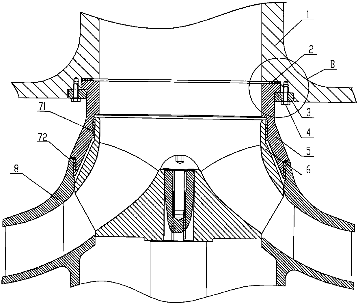
A technology of labyrinth seal and sealing structure, which is applied to the components, pumps, pump elements, etc. of the pumping device for elastic fluid, which can solve the problem of reduced concentricity between the mouth ring and the centrifugal pump, limited effect of preventing backflow, and medium dissipation. It can improve the efficiency of equipment, prolong its service life, and achieve the effect of non-destructive disassembly and assembly.

Active Publication Date: 2018-12-18
ZHEJIANG UNIV
View PDF5 Cites 3 Cited by
  • Summary
  • Abstract
  • Description
  • Claims
  • Application Information

AI Technical Summary

Problems solved by technology

[0003] Most of the existing mouth rings adopt the sealing form of smooth mouth rings, relying on the throttling gap to increase the flow resistance of the medium, thereby reducing leakage and achieving the sealing effect, but this structure has low dissipation of the medium inside the cavity and prevents backflow Limited; most of the existing center-open structure mouth rings are only connected by bolts, the coaxiality between the mouth ring and the centrifugal pump is reduced, which is easy to cause misalignment, vibration and noise, causing impeller and pump shaft failure, and reducing the service life

Method used


Image

  • Special-shaped tooth dual labyrinth seal structure and special-shaped tooth impeller ring seal structure for nuclear main pump and with locating function
  • Special-shaped tooth dual labyrinth seal structure and special-shaped tooth impeller ring seal structure for nuclear main pump and with locating function
  • Special-shaped tooth dual labyrinth seal structure and special-shaped tooth impeller ring seal structure for nuclear main pump and with locating function

Examples


Embodiment Construction

[0024] The present invention will be described in detail below in conjunction with the accompanying drawings. The description in this part is only exemplary and explanatory, and should not have any limiting effect on the protection scope of the present invention.

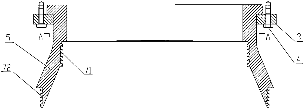
[0025] The invention provides a special-shaped tooth double labyrinth seal structure, such as Figure 5 As shown, it includes a plurality of sealing teeth, the sealing teeth are inclined to the fluid inlet side, and the leeward surface adopts a concave arc structure, and the arc angle of the arc structure is 35-60°; the formation between two adjacent sealing teeth The first sealing cavity 701; the height of the sealing teeth is the depth h of the first sealing cavity 701, and the inclination angle of the sealing teeth is the inclination of the first sealing cavity 701 The distance between two adjacent sealing teeth is the width b of the first sealing cavity 701; the upper part of the first sealing cavity 701 is pro...


PUM


Abstract

The invention belongs to the technical field of fluid machinery and clearance seals, and particularly relates to a special-shaped tooth dual labyrinth seal structure and a special-shaped tooth impeller ring seal structure for a nuclear main pump and with a locating function. Seal teeth of the special-shaped tooth dual labyrinth seal structure incline towards the fluid inlet side, an inwards-concave arc structure is adopted by the leeside, a small seal cavity of a parallelogram structure is formed on the upper portion of a large seal cavity of a parallelogram-like structure, and a dual labyrinth seal is formed. An impeller ring and the outer edge of an impeller water inlet and the impeller ring and the inner wall of the front edge of a guide vane are sealed through the special-shaped toothdual labyrinth seal structure. A seal gasket is arranged between the impeller ring and a pump case for axial locating, and liquid backflow is avoided. A special-shaped tooth shape correction coefficient constraint function is obtained through calculation based on bulk analysis, the optimal design key size can be determined within a short time, and the adverse effect of clearance leaking of the impeller ring to the nuclear main pump is reduced.

Description

technical field [0001] The invention belongs to the technical field of fluid machinery and gap sealing, and more specifically relates to a special-shaped tooth double-labyrinth sealing structure and a special-shaped tooth mouth ring sealing structure with positioning for a nuclear main pump. Background technique [0002] When the vane pump is working, there is a certain gap between the high-speed rotating impeller and the fixed pump body, and between the impeller and the guide vane. The pressure difference between the two ends of the gap causes the fluid to flow from the high-pressure chamber to the low-pressure chamber, resulting in leakage and energy loss. Therefore, in engineering, a sealing ring will be set at the gap to reduce the leakage of the medium. In addition, the setting of the sealing ring can also protect the main parts of the pump from wear, improve the water flow state at the pump inlet, and improve the pump efficiency. [0003] Most of the existing mouth ri...

Claims


Application Information

Patent Timeline
Patent Type & Authority Applications(China)
IPC IPC(8): F04D29/08
CPCF04D29/086
Inventor 许忠斌刘聪王悦荟阮晓东王鹏飞崔赟
Owner ZHEJIANG UNIV
Why Eureka
Eureka Blog
Learn More