
Novel sealing sleeve used on turbo-supercharger

A turbocharger and sealing sleeve technology, which is applied to the components of pumping devices for elastic fluids, machines/engines, non-variable displacement pumps, etc. Pressure and suction, can not solve the problem of supercharger oil leakage, etc., to achieve the effect of simple structure

Pending Publication Date: 2018-12-18
HUNAN TYEN MACHINERY
View PDF2 Cites 0 Cited by
  • Summary
  • Abstract
  • Description
  • Claims
  • Application Information

AI Technical Summary

Problems solved by technology

[0004] For example, the patent ZL201520888694.7 provides a sealing sleeve with an oblique oil throwing plate and a middle oil throwing plate, and an oil throwing groove is arranged between the bevel oil throwing plate and the middle oil throwing plate. This structure can effectively improve the turbocharger. High-speed sealing effect, but it cannot solve the problem of oil leakage of the supercharger under low speed and low load conditions
[0005] For example, the patent ZL201621450748.2 provides a sealing sleeve with double oil throwing pan, double oil throwing groove and double ring structure, which can improve the sealing effect of the supercharger to a certain extent, but the diameter of the oil throwing pan and the sealing ring of this structure The outer diameters of the grooves are the same size, and the oil throwing plate diameter is too small, the effect of oil throwing is not ideal, and the design of the oil throwing groove and the sealing ring groove of this structure is too close, the lubricating oil is easily sucked out by the negative pressure, and finally causes the supercharger to leak oil

Method used


Image

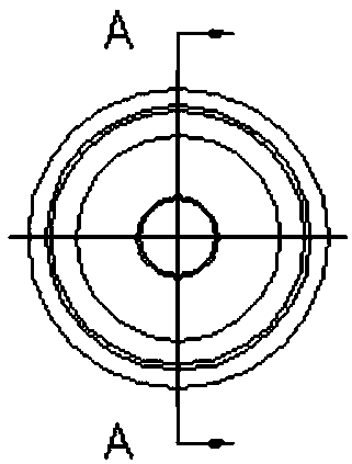
  • Novel sealing sleeve used on turbo-supercharger
  • Novel sealing sleeve used on turbo-supercharger

Examples


Embodiment Construction

[0021] The detailed structure of the present invention will be further described below in conjunction with the accompanying drawings and specific embodiments.

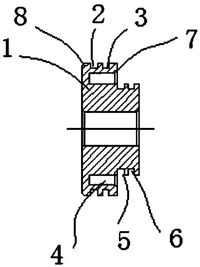
[0022] see figure 1 , a new type of sealing sleeve used on a turbocharger shown in the figure, wherein the A end of the sealing sleeve is close to the oil cavity of the supercharger bearing body, and the B end of the sealing sleeve is in contact with the compressor impeller. The A end is provided with an oil throwing pan 1, and the end face of the oil throwing pan 1 is provided with a chamfer 8. A first sealing ring groove is provided on the outer circle of the oil flinger 1 ; the first sealing ring groove can be one or divided into two sealing ring grooves 2 and 3 .

[0023] A second sealing groove is arranged on the outer circle of the B end of the sealing sleeve. The second seal ring groove can be one or divided into two seal ring grooves 5 and 6 . The end surface 7 of the oil thrower 1 adjacent to the sealing ri...


PUM


Abstract

The invention discloses a novel sealing sleeve used on a turbo-supercharger. The end A of the sealing sleeve is close to a supercharger bearing body oil cavity, and the end B of the sealing sleeve makes contact with a gas compressor impeller. The novel sealing sleeve is characterized in that an oil flinger is arranged at the end A of the sealing sleeve, and a first sealing ring groove is formed inthe outer circle of the oil flinger; and a second sealing ring groove is formed in the outer circle of the end B of the sealing sleeve. In addition, a labyrinth type annular groove is formed betweenthe end A and the end B of the sealing sleeve. The sealing sleeve is simple in structure and low in cost, and the negative pressure resisting capacity of the turbo-supercharger can be effectively improved. The sealing sleeve is suitable for diesel oil and gas with high inflow negative pressure, gasoline engine turbo-superchargers and the like.

Description

technical field [0001] The invention relates to the technical field of turbochargers, in particular to a novel sealing sleeve used on turbochargers. Background technique [0002] With the continuous improvement of internal combustion engine strengthening and increasingly stringent emission standards, turbocharging technology has become one of the most critical measures to improve the economy, power and emission standards of internal combustion engines. With the development of diesel and gasoline engines, as well as the turbocharging technology of unmanned aircraft, the intake negative pressure it bears is also increasing. Since the sealing sleeve is a key component in the sealing structure of the compressor end of the turbocharger, its impact on The sealing ability of the supercharger and even the reliability of the supercharger have a very important influence. The structure of the seal sleeve determines the mechanical sealing capability of the compressor end of the turboch...

Claims


Application Information

Patent Timeline
IPC IPC(8): F02B39/14F04D29/08
CPCF02B39/14F04D29/083
Inventor 欧永健王星封金虎朱光前肖明鹏刘麟
Owner HUNAN TYEN MACHINERY
Learn More