Focusing system and method of shield tunneling machine

A technology of focusing system and shield machine, applied in the field of shield, which can solve the problems of affecting the accuracy of apparent resistivity measurement, false alarms, etc.

Pending Publication Date: 2018-12-18
THE 22ND RES INST OF CHINA ELECTRONICS TECH GROUP CORP
View PDF0 Cites 1 Cited by
  • Summary
  • Abstract
  • Description
  • Claims
  • Application Information

AI Technical Summary

Problems solved by technology

[0004] The embodiment of the present invention provides a focusing system and method of a shield machine, to at least solve the technical problem that the focusing system using hardware focusing in the related art affects the measurement accuracy of apparent resistivity and easily causes system false alarms

Method used


Image

  • Focusing system and method of shield tunneling machine
  • Focusing system and method of shield tunneling machine
  • Focusing system and method of shield tunneling machine

Examples


Embodiment approach

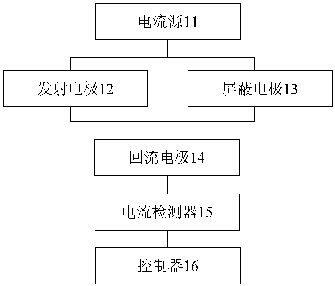
[0055]The cutter head of the shield machine (or TBM) is used as the emission electrode A0 electrode, the shield of the shield machine (or TBM) is used as the shield electrode A1 electrode, the Rogowski coil is installed between the cutter head and the shield as the current measurement coil, and the return electrode B and reference electrode N are placed on ground anchors behind (eg, 300m-500m behind) the shield machine (or TBM). The implementation of digital focus is as follows:

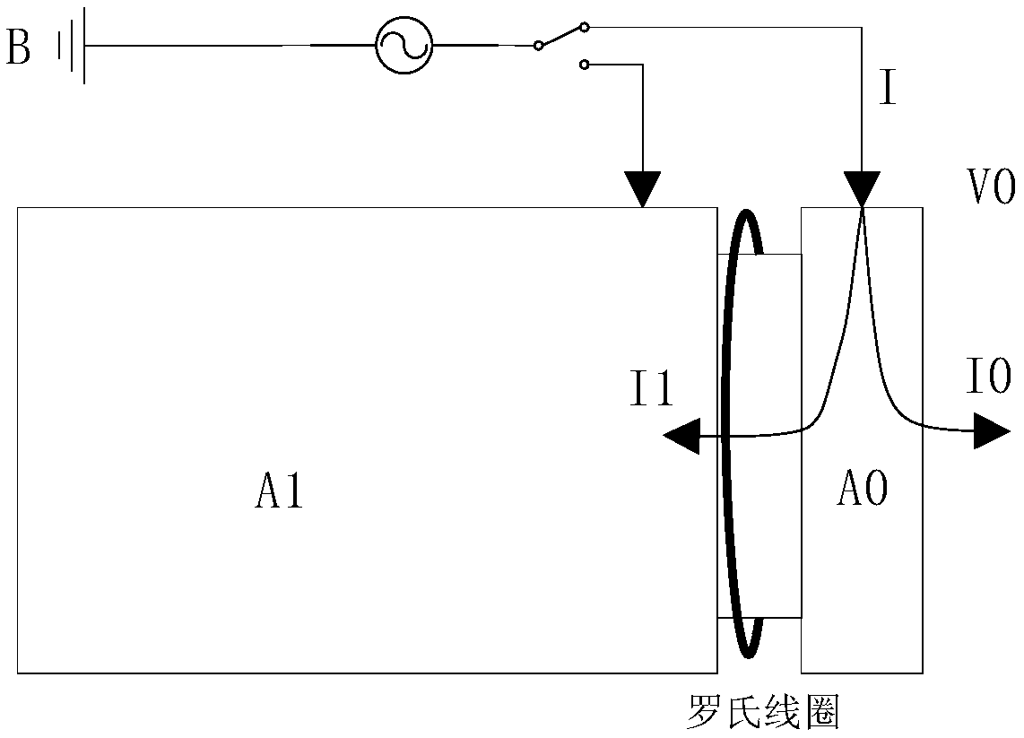
[0056] Mode 1: figure 2 It is a schematic structural diagram of the first mode circuit according to the preferred implementation mode of the embodiment of the present invention, such as figure 2 As shown, power is supplied to the cutter head (A0 electrode) and B electrode, the total power supply current is I, and the current flows into the cutter head and is divided into two parts, one part of the current (I0) directly flows into the formation and returns to the B electrode, and the other part of ...


PUM


Abstract

The invention discloses a focusing system and method of a shield tunneling machine. The system comprises a current source, an emission electrode, a shielding electrode, a backflow electrode and a current detector. Under the condition that the current source provides power for the emission electrode and the backflow electrode, the shield tunneling machine emits current by use of a first mode. Underthe condition that the current source provides power for the shielding electrode and the backflow electrode, the shielding tunneling machine emits current by use of a second mode. The focusing systemcomprises a controller. The controller is used for controlling the superposition proportion of the first mode and the second mode when the focusing system emits current by use of the first mode and the second mode so as to allow the current detected by the current detector to be zero. According to the invention, a technical problem is solved that by use of a focusing system of the hardware focusing, measurement precision of apparent resistivity is affected and system error reporting is easily caused in the prior art.

Description

technical field [0001] The invention relates to the field of shield tunneling, in particular to a focusing system and method for a shield tunneling machine. Background technique [0002] Among related technologies, BEAM (Bore-Tunneling Electrical Ahead Monitoring) technology is a technology that uses electrical methods for tunnel geological prediction ahead of time, and adopts the induced polarization method. In this method, ring-shaped electrodes are arranged on the face of the face and measuring electrodes are arranged on the inside in front of the face of the face. By emitting a shielding current into the shielding electrode and a measuring current into the measuring electrode, the current is focused into the rock mass to be detected. Predict the integrity and water content of the rock mass ahead of the face by analyzing changes in electrical energy storage energy parameters related to pores in the rock mass. When using BEAM technology, the cutter head and shield body o...

Claims


Application Information

Patent Timeline
IPC IPC(8): E21D9/00E21D9/06
CPCE21D9/003E21D9/06
Inventor 杨艳军郑俊祥张克
Owner THE 22ND RES INST OF CHINA ELECTRONICS TECH GROUP CORP
Why Eureka
Try Eureka