
Oilfield Field Tubing Transportation Method

A technology of oil pipes and oil fields, which is applied in the field of oil pipe transportation and loading on the oil field site, which can solve the problems of high labor intensity, long time consumption for shipment, and low production timeliness, and achieve the effect of ensuring normal production and solving high transportation costs

Active Publication Date: 2019-12-10
PETROCHINA CO LTD
View PDF12 Cites 0 Cited by
  • Summary
  • Abstract
  • Description
  • Claims
  • Application Information

AI Technical Summary

Problems solved by technology

Among the above two oil pipe loading methods, the first one is mechanical operation. It is more convenient to hang the wire rope cover manually. The capital is 3,474 yuan, and this mode of operation has been canceled under the current environment of low oil prices
The second type of person is to carry the oil pipes one by one, in groups of two. At present, there are 46 oil pipe transporters in the preparation team, and 23 trips. Every day, the oil pipes are transported from the oil pipe stack to the four-wheeled vehicle. In terms of labor intensity, the average oil pipe is 300Kg. Long-term operation like this is easy to make people feel tired, and when the two cooperate, it is easy to cause accidents where a single person lifts the pipe and injures people. Secondly, it takes a long time
In the current society and the era of advanced technology, there are still many hidden dangers in the use of this backward technology in oil field production. At the same time, it takes about 90 minutes to install a car of oil pipes, and the production time is low. Once the oil pipes take a long time to ship, it will affect the later stage. All production connections

Method used


Image

  • Oilfield Field Tubing Transportation Method
  • Oilfield Field Tubing Transportation Method
  • Oilfield Field Tubing Transportation Method

Examples


Embodiment Construction

[0036] The details of the present invention can be understood more clearly with reference to the accompanying drawings and the description of specific embodiments of the present invention. However, the specific embodiments of the present invention described here are only for the purpose of explaining the present invention, and should not be construed as limiting the present invention in any way. Under the teaching of the present invention, the skilled person can conceive any possible modification based on the present invention, and these should be regarded as belonging to the scope of the present invention. It should be noted that when an element is referred to as being “disposed on” another element, it may be directly on the other element or there may also be an intervening element. When an element is referred to as being "connected to" another element, it can be directly connected to the other element or intervening elements may also be present. The terms "mounted", "connec...


PUM


Abstract

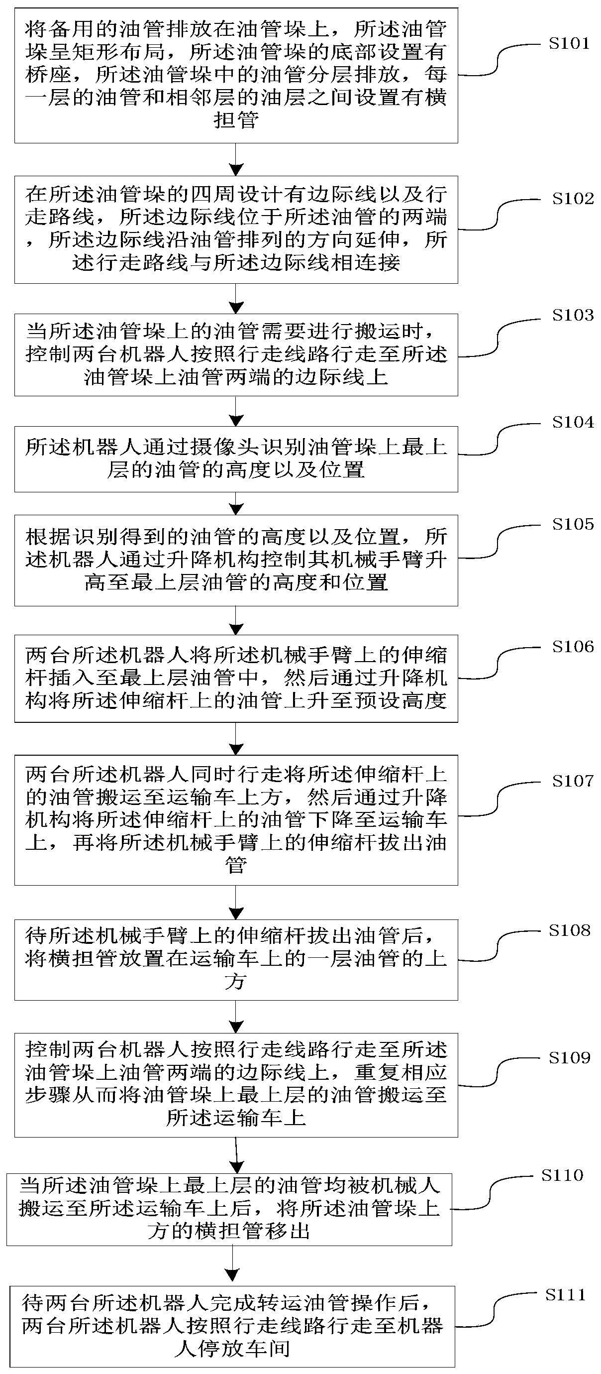
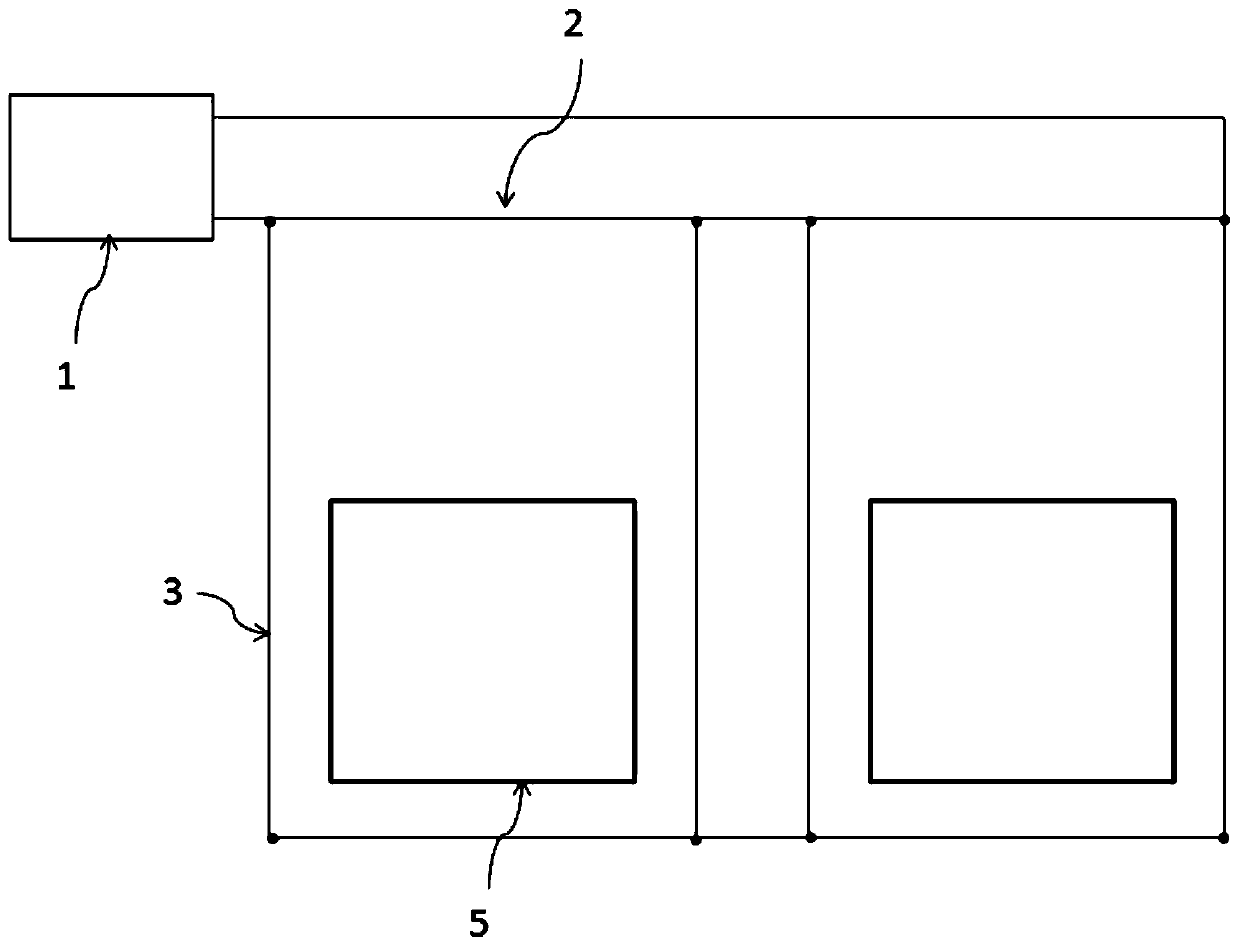
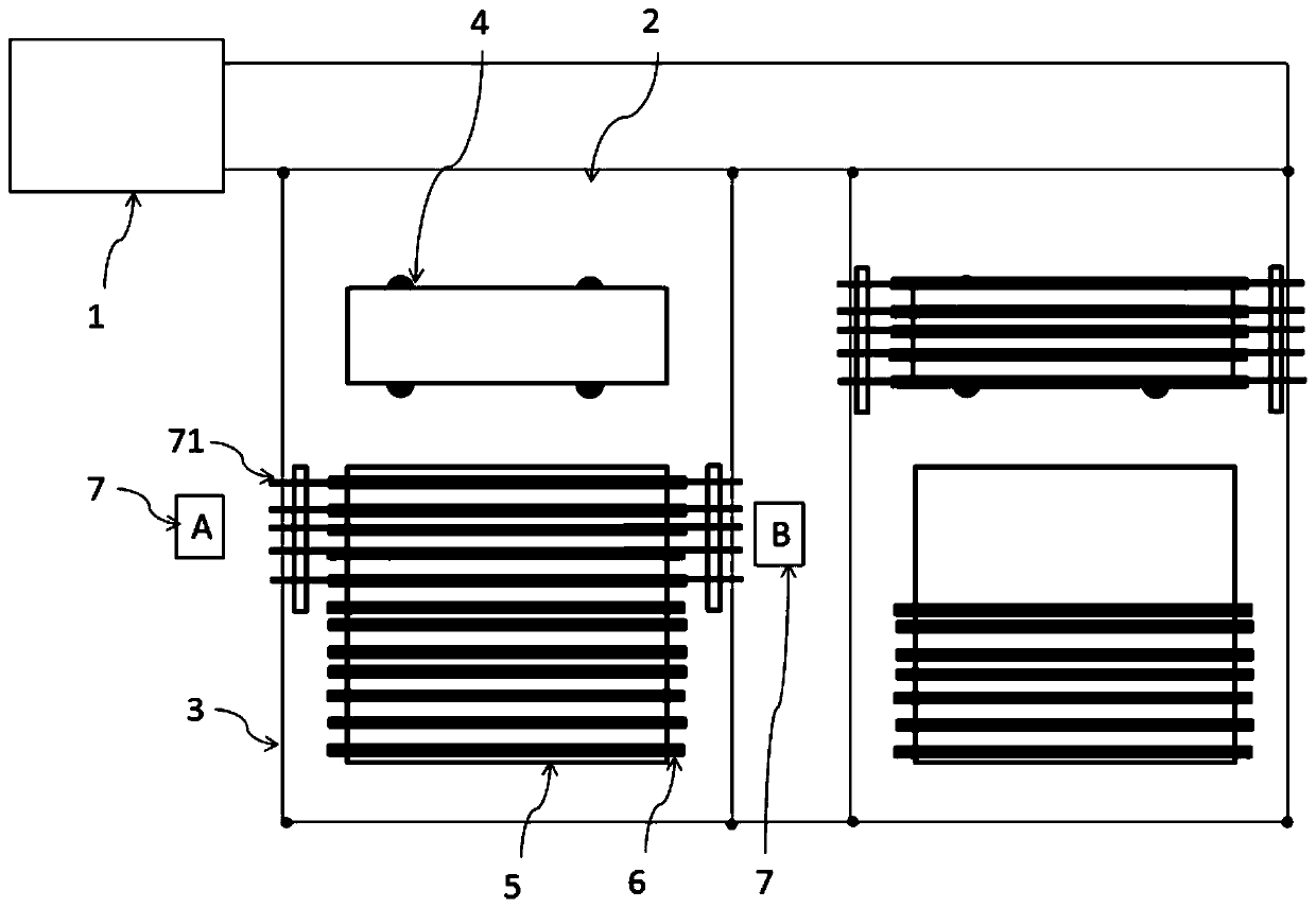
The invention discloses an oilfield field oil pipe transporting and loading method which relates to the field of oilfield production. The method comprises the following steps of placing standby oil pipes on an oil pipe stack which has a rectangular layout, wherein the bottom of the oil pipe stack is provided with a bridge seat, the oil pipes in the oil pipe stack are placed in a layered manner, and a cross-arm pipe is arranged between the oil pipes in one layer and the oil pipe in the adjacent layer; designing boundary lines and a walking line at periphery of the oil pipe stack, wherein the boundary lines are arranged at two ends of the oil pipes and extend in an oil pipe arrangement direction, the walking line is connected with the boundary lines; when the oil pipes in the oil pipe stackrequire conveying, making two robots walk along a walking line to the boundary lines at two ends of the oil pipes in the oil pipe stack; identifying the height and position of the oil pipe on the topmost layer on the oil pipe stack by the robot through a camera; etc. The oilfield field oil pipe transporting and loading method can realize high-efficiency, standard and labor-saving transportation ofthe oil pipes, thereby ensuring normal production of the oilfield.

Description

technical field [0001] The invention relates to the field of oil field production, in particular to a method for transporting and loading oil pipes on site in an oil field. Background technique [0002] In the development and production of oilfields, the production preparation team is responsible for the transportation, cleaning and maintenance of pipes in all oilfield production. Taking pipe transportation as an example, the production preparation brigade of Jinzhou Oil Production Plant ships about 1,500 to 2,000 oil pipes per day. Currently, the production preparation brigade of the oil production plant has 52 stacks of oil pipes, and nearly 260,000 oil pipes of various types and models. It is an important basis for ensuring oilfield production and operation. [0003] In production, there are two main ways to ship oil pipes, namely, mechanical and manual. The mechanical method is to use the crane and the truck to cooperate, lift the oil pipes in batches and install them ...

Claims


Application Information

Patent Timeline
Patent Type & Authority Patents(China)
IPC IPC(8): E21B19/14
CPCE21B19/14
Inventor 贾财华赵云明龚乃建段效威孙立超李洪波黄海礁蒋明姜英鹏要步旻
Owner PETROCHINA CO LTD
Learn More