Slope support structure and support method

A technology for supporting structures and slopes, applied in infrastructure engineering, excavation, construction, etc., can solve problems such as collapse, insufficient support force, poor stability, etc., to achieve large-scale implementation, simple and effective methods, and stability Good results

Inactive Publication Date: 2018-12-18
EAST CHINA UNIV OF TECH
View PDF5 Cites 10 Cited by
  • Summary
  • Abstract
  • Description
  • Claims
  • Application Information

AI Technical Summary

Problems solved by technology

[0003] At present, most of the existing slope support structures have the problem of poor stability. The supports that have been supported for a long time will settle under the conditions of wind, sun, rain and snow erosion, which will eventually lead to insufficient support and collapse of the supports, resulting in engineering accidents. or road safety accident

Method used


Image

  • Slope support structure and support method
  • Slope support structure and support method
  • Slope support structure and support method

Examples


Embodiment 1

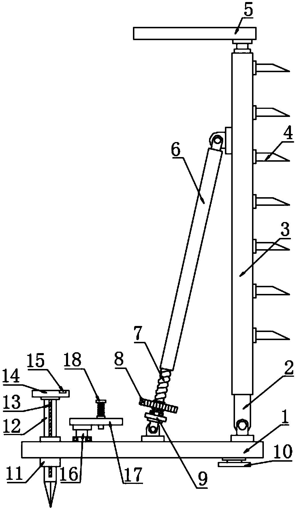
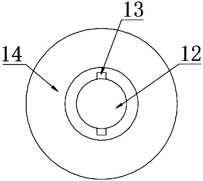
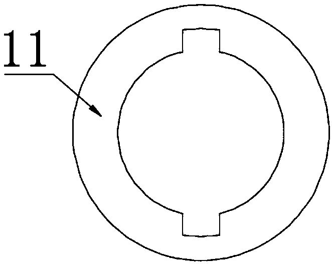
[0028] In the embodiment of the present invention, a slope support structure includes a base plate 1, a telescopic plate 3, a threaded cylinder 6, a screw rod 7, a drill rod 12 and a pressure plate 17; the right end of the base plate 1 is hinged with a fixed plate 2, and the fixed plate 2. The upper part is covered with a telescopic plate 3, the left surface of the upper part of the telescopic plate 3 is rotated and connected to the upper end of the threaded cylinder 6, the lower part of the threaded cylinder 6 is threaded to connect with the screw rod 7, and the bearing at the lower end of the screw rod 7 is connected to the movable base 9 by rotation, and the movable base 9 is connected to the bottom plate 1 Rotational connection, the lower part of the screw rod 7 is fixedly connected with the adjustment wheel 8, wherein a triangle is formed by the bottom plate 1, the connecting body of the fixed plate 2 and the telescopic plate 3, the connecting body of the threaded cylinder ...

Embodiment 2

[0032] In the embodiment of the present invention, a slope support structure includes a base plate 1, a telescopic plate 3, a threaded cylinder 6, a screw rod 7, a drill rod 12 and a pressure plate 17; the right end of the base plate 1 is hinged with a fixed plate 2, and the fixed plate 2. The upper part is covered with a telescopic plate 3, the left surface of the upper part of the telescopic plate 3 is rotated and connected to the upper end of the threaded cylinder 6, the lower part of the threaded cylinder 6 is threaded to connect with the screw rod 7, and the bearing at the lower end of the screw rod 7 is connected to the movable base 9 by rotation, and the movable base 9 is connected to the bottom plate 1 Rotational connection, the lower part of the screw rod 7 is fixedly connected with the adjustment wheel 8, wherein a triangle is formed by the bottom plate 1, the connecting body of the fixed plate 2 and the telescopic plate 3, the connecting body of the threaded cylinder ...


PUM


Abstract

The invention discloses a slope support structure and a support method. The left side of a bottom plate is fixedly connected with a sleeve. The sleeve penetrates through the bottom plate. A drill rodis sleeved in the sleeve. Limiting convex strips are symmetrically arranged on the two sides of the drill rod. Grooves are symmetrically arranged on the two sides of the inner ring of the sleeve. Thelimiting convex strips are embedded in the grooves of the inner ring of the sleeve. The lower portion of the drill rod is pointed. The upper end of the drill rod is fixedly connected with a top disc.A limiting hole is formed in the upper surface of the right side of the top disc. A rotating shaft is arranged on the right side of the sleeve. The lower end of the rotating shaft is in bearing rotaryconnection with the upper surface of the bottom plate, and the upper end of the rotary shaft is fixedly connected with a press plate. The press plate is eccentrically arranged at the upper end of therotating shaft. A through hole is formed in the middle of the press plate, and a pin shaft is connected in the through hole in an inserted manner. By means of the support structure, a triangle has stability, a lead screw is driven to rotate by rotating an adjusting wheel, the lead screw drives a threaded barrel to move, then a telescopic plate is driven to stretch out and draw back along a fixedplate to adjust the inclination angle while moving, and slopes of different angles can be supported.

Description

technical field [0001] The invention relates to the field of environmental protection, in particular to a slope support structure and a support method. Background technique [0002] It refers to the slope with a certain slope made on both sides of the roadbed to ensure the stability of the roadbed. Slopes are often supported by special linings or other structures to prevent collapse, ensure construction or road safety, and improve road safety. When supporting the slope, due to long-term stress, it is inevitable that stress concentration or yielding of the support force will cause the support to deform or even collapse, causing the slope to slide. [0003] At present, most of the existing slope support structures have the problem of poor stability. The supports that have been supported for a long time will settle under the conditions of wind, sun, rain and snow erosion, which will eventually lead to insufficient support and collapse of the supports, resulting in engineering ...

Claims


Application Information

Patent Timeline
Patent Type & Authority Applications(China)
IPC IPC(8): E02D17/20
CPCE02D17/20
Inventor 李明东薛凯喜朱丽萍吉植强徐长节查文华
Owner EAST CHINA UNIV OF TECH
Why Eureka
Try Eureka