Supporting mechanism for discharging end part

A discharge end and end piece technology, which is applied in the field of the support mechanism of the discharge end piece, can solve the problems of shortening the displacement stroke of the discharge end piece, reducing the manufacturing efficiency, and deriving energy waste.

Active Publication Date: 2018-12-18
KING STEEL MACHINERY
View PDF4 Cites 0 Cited by
  • Summary
  • Abstract
  • Description
  • Claims
  • Application Information

AI Technical Summary

Problems solved by technology

[0002] In order to solve the known polymer raw material supply technology such as extrusion or injection, the discharge end piece moves downward from the top of the vertical mold station, and when the mold in the mold station abuts for material supply, the discharge end needs to be Parts move through the top plate above the warp die station, but there is a lack of too long displacement stroke, which leads to the waste of derived energy and reduces the efficiency of manufacturing. In the prior case of the new patent No. M256813 in Taiwan, China, there is a vertical mold The top plate of the station is provided with an open sliding space for the discharge end piece to slide in, so that the discharge end piece can move between different mold stations without moving out of the top plate, so as to shorten the displacement stroke of the discharge end piece during feeding
[0003] Since the discharge end piece abuts against the mold to form a polymer material flow channel, the abutment between them must be tight to avoid seepage of the polymer material. The effect of shortening the feeding stroke is achieved, but when the discharge end piece is in contact with the mold after the injection stroke moves, the reaction force abutting against the mold will be transmitted to the known polymer raw material supply device, In particular, it is not an ideal technology for the columnar heating extruder that is directly connected to the discharge end piece for hot-melt polymer raw materials.

Method used


Image

  • Supporting mechanism for discharging end part
  • Supporting mechanism for discharging end part
  • Supporting mechanism for discharging end part

Examples


Embodiment Construction

[0031] Hereinafter, a preferred embodiment of the present invention will be described in detail together with the drawings.

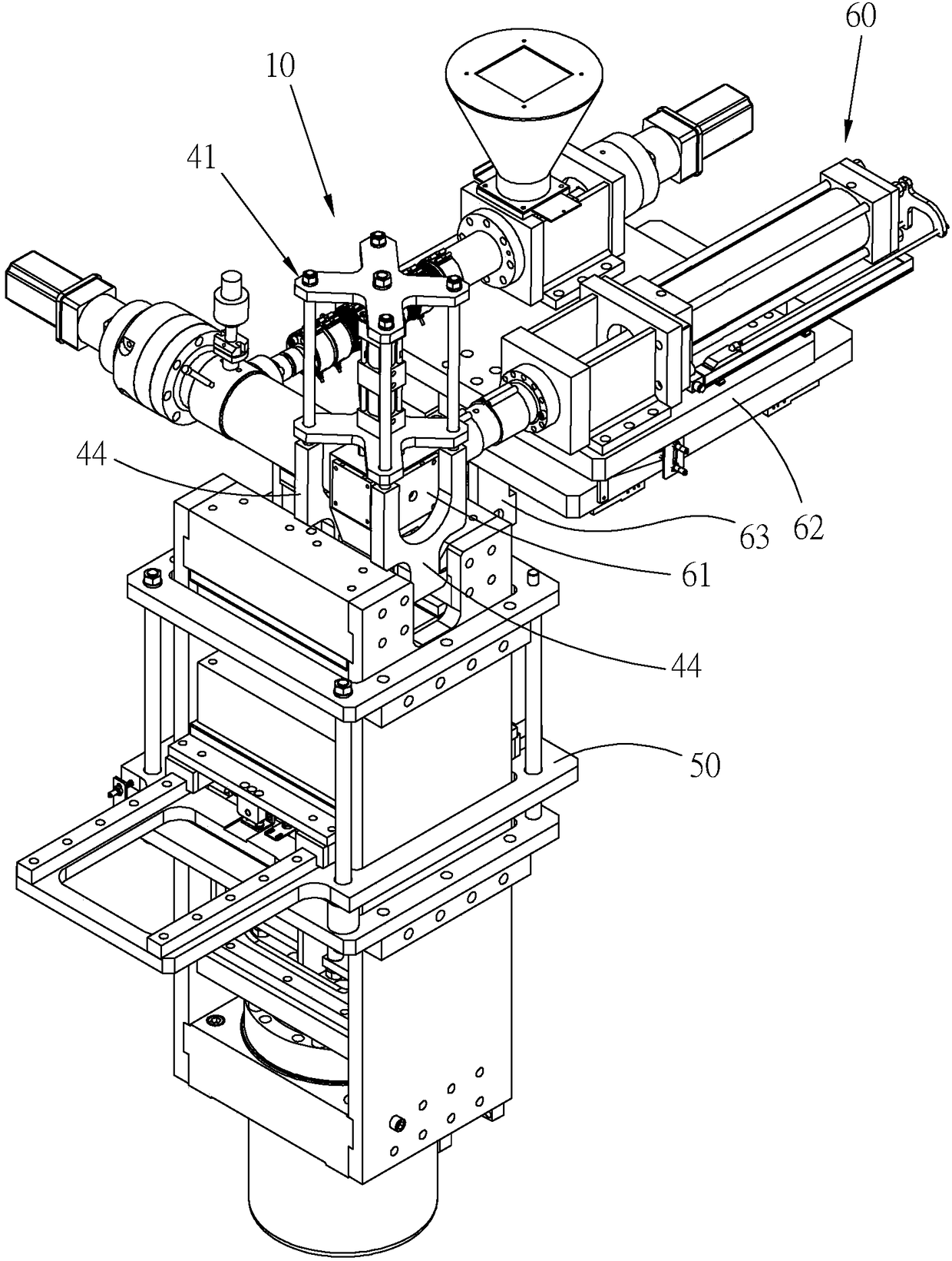
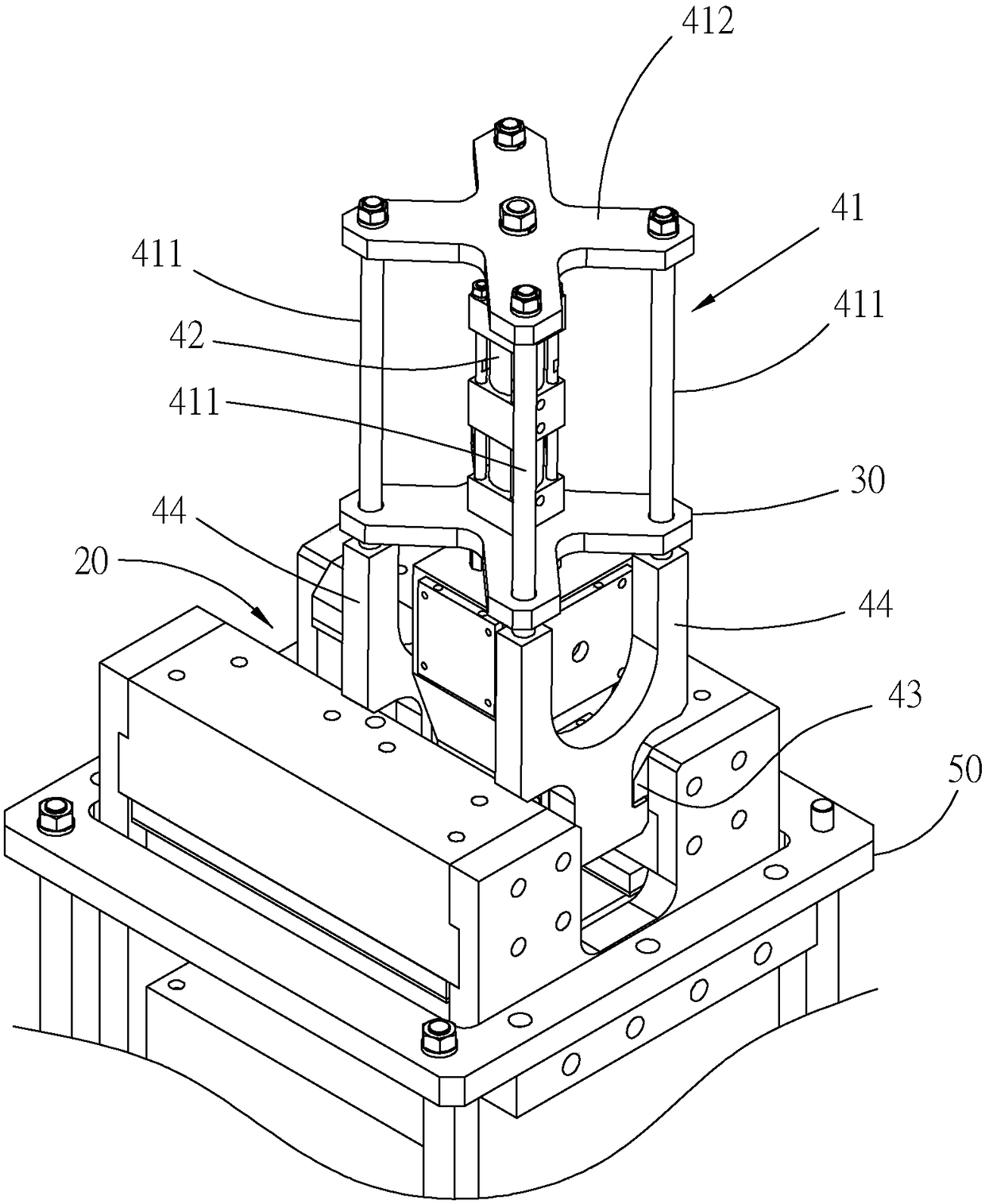
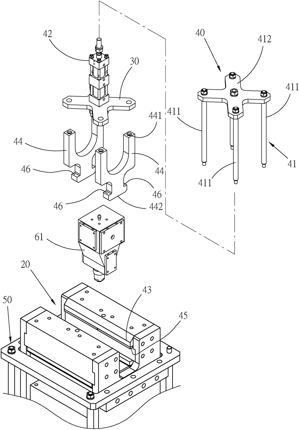
[0032] First, see Figure 1 to Figure 3 As shown, in a preferred embodiment of the present invention, the supporting mechanism 10 of the discharge end piece mainly includes a movable space 20 , a seating portion 30 and a supporting portion 40 .

[0033] The movable space 20 is a groove with an opening facing upwards and two sides are hollow, and is recessed on the top end surface of a clamping mechanism 50 .

[0034] The seat portion 30 is plate-shaped, and is fixed above an injection end piece 61 located above the opening of the movable space 20 , so that the discharge end piece 61 is interposed between the clamping mechanism 50 and the seat portion 30 .

[0035] The supporting part 40 has a sliding part 41, which is slidably arranged on the seat part 30, and can move back and forth linearly along the opening direction of the activity space 20, and a...


PUM


Abstract

The invention provides a supporting mechanism for a discharging end part. The supporting mechanism for the discharging end part is arranged between the discharging end part of a macromolecular raw material supply device and a vertical-type mold holding mechanism of a macromolecular molding formation device, wherein the discharging end part is located above the mold holding mechanism and can move from a far position to a close position in the base feeding direction opposite to the mold holding mechanism in a recoverable mode, and the supporting mechanism for the discharging end part can providesupport for the discharging end part at the close position in the direction opposite to the base feeding direction.

Description

technical field [0001] The invention relates to polymer molding processing technology, in particular to a support mechanism for a discharge end piece. Background technique [0002] In order to solve the known polymer raw material supply technology such as extrusion or injection, the discharge end piece moves downward from the top of the vertical mold station, and when the mold in the mold station abuts for material supply, the discharge end needs to be Parts move through the top plate above the warp die station, but there is a lack of too long displacement stroke, which leads to the waste of derived energy and reduces the efficiency of manufacturing. In the prior case of the new patent No. M256813 in Taiwan, China, there is a vertical mold The top plate of the station is provided with an open sliding space for the discharge end piece to slide in, so that the discharge end piece can move between different mold stations without moving out of the top plate, so as to shorten the...

Claims


Application Information

Patent Timeline
Patent Type & Authority Applications(China)
IPC IPC(8): B29C47/36B29C47/58B29C45/46B29C45/58
CPCB29C45/46B29C45/58
Inventor 陈法胜
Owner KING STEEL MACHINERY
Why Eureka
Try Eureka