
Composite heat-preservation system steel bar truss welding forming production line and truss production method

A steel truss and composite thermal insulation technology, which is applied to other manufacturing equipment/tools, manufacturing tools, etc., can solve problems such as low production efficiency, poor quality of triangular trusses, and poor mesh positioning

Active Publication Date: 2018-12-18
河北骄阳焊工有限公司
View PDF8 Cites 4 Cited by
  • Summary
  • Abstract
  • Description
  • Claims
  • Application Information

AI Technical Summary

Problems solved by technology

At present, the main production method is to weld the large mesh first, then cut and bend it by a shearing machine, and move the cut mesh to the bending machine. During the bending process, there are the following defects: First, when the mesh moves High labor intensity and low production efficiency; second, due to the poor positioning of the mesh, the quality of the produced triangular truss is poor, and it is easy to cause uneven wall thickness during use

Method used


Image

  • Composite heat-preservation system steel bar truss welding forming production line and truss production method
  • Composite heat-preservation system steel bar truss welding forming production line and truss production method
  • Composite heat-preservation system steel bar truss welding forming production line and truss production method

Examples


Embodiment Construction

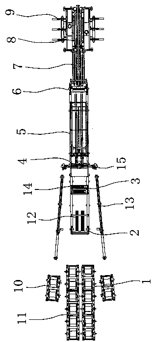
[0093] The structure and operating principle of the steel bar truss welding and forming production line of the composite thermal insulation system of the present invention and the method for producing the truss will be further described in detail below in conjunction with the accompanying drawings and specific embodiments.

[0094] like figure 1 , figure 2 , image 3 , Figure 4 , Figure 5 , Image 6 , Figure 7 , Figure 8 , Figure 9 , Figure 10 , Figure 11 , Figure 12 and Figure 13 As shown, the structure schematic diagram of the steel bar truss welding and forming production line of the composite heat preservation system of the present invention, the steel bar truss welding and forming production line of the composite heat preservation system of the present invention includes a wire-feeding mechanism 1, a material slowing mechanism 2, a straightening mechanism 3, a welding mechanism 4, and a stretching mechanism 5. Net cutting mechanism 6, mesh feeding mec...


PUM


Abstract

The invention belongs to the technical field of wire mesh machining device, and discloses a composite heat-preservation system steel bar truss welding forming production line and a truss production method. The composite heat-preservation system steel bar truss welding forming production line is mainly technically characterized in that a straightening mechanism, a welding mechanism, a net pull mechanism, a net cutting mechanism, a net piece sending mechanism, a bending mechanism and a discharging mechanism are included; the welding mechanism comprises one or more pairs of horizontal wire positioning mechanisms, each horizontal wire positioning mechanism comprises a fixing base and a fixing bracket, a spring steel sheet is arranged on the upper portion of each fixing bracket, a fixed ruler head is arranged at the front end of each spring steel sheet, a transverse wire penetrating hole is formed in each fixed ruler head, a wire outlet is formed in the front end of each wire penetrating hole, and a magnetic block is arranged at the rear end of each wire penetrating hole; and the bending mechanism comprises an upper bending cutter and a lower bending cutter corresponding to the upper bending cutter, a wire-jacking clamping groove with the section being semicircular is formed in the upper portion of the lower bending cutter, and a net piece conveying rack is located between the upperbending cutter and the lower bending cutter. When a net piece is pulled forwards, a transverse bar is pulled out from the wire outlet, the net piece is uplifted, abrasion of a lower electrode is avoided, the bent net piece is hooked by a discharging hook, and discharging is facilitated.

Description

technical field [0001] The invention belongs to the technical field of wire mesh processing devices, and in particular relates to a method for producing the truss in a welding and forming production line of a steel bar truss of a composite thermal insulation system. Background technique [0002] In construction and other wire mesh applications, especially in composite thermal insulation systems, triangular truss mesh is used in many places. At present, the main production method is to weld the large mesh first, then cut and bend it by a shearing machine, and move the cut mesh to the bending machine. During the bending process, there are the following defects: First, when the mesh moves The labor intensity is high and the production efficiency is low; secondly, due to the poor positioning of the mesh, the quality of the produced triangular truss is poor, and it is easy to cause uneven thickness of the wall during use. Contents of the invention [0003] The first technical ...

Claims


Application Information

Patent Timeline
IPC IPC(8): B23P23/06
CPCB23P23/06
Inventor 张中盼张学勇周志成王斌齐仕元
Owner 河北骄阳焊工有限公司
Learn More