
Single line conveying automatic glue dispensing production line

An automatic glue dispensing and production line technology, which is applied to the surface coating liquid device, pretreatment surface, coating, etc., can solve the problems of uneven glue coating, difficult installation and fixation of glass plates, and difficult installation and fixation of glass substrates And other issues

Pending Publication Date: 2018-12-18
河南天扬光电科技有限公司
View PDF1 Cites 0 Cited by
  • Summary
  • Abstract
  • Description
  • Claims
  • Application Information

AI Technical Summary

Problems solved by technology

[0002] In the production process of the LCD screen, the side of the glass plate needs to be coated with glue. The traditional glue coating method will lay the glass plate flat, and the glue will flow down due to the influence of gravity, and it is easy to apply uneven glue. Another extreme method is adopted. The glass plate is placed vertically, and the glue will not be affected by gravity at all, but the glass plate is not easy to install and fix. For example, the Chinese invention patent with application number 2017201052197 discloses a OLED side glue curing system, and the glass substrate is not easy to install and fix. , and use the rotating shaft to adjust the position of the stage, the positioning is not reliable; and the glue itself is sticky, it does not need to be completely vertical when applying glue on the side of the glass plate, but can be tilted at a certain angle; When the substrate is dispensed, the material is manually loaded, and the glass plate is placed in a fixed position and picked up by the robot, resulting in low production efficiency.

Method used


Image

  • Single line conveying automatic glue dispensing production line
  • Single line conveying automatic glue dispensing production line
  • Single line conveying automatic glue dispensing production line

Examples


Embodiment Construction

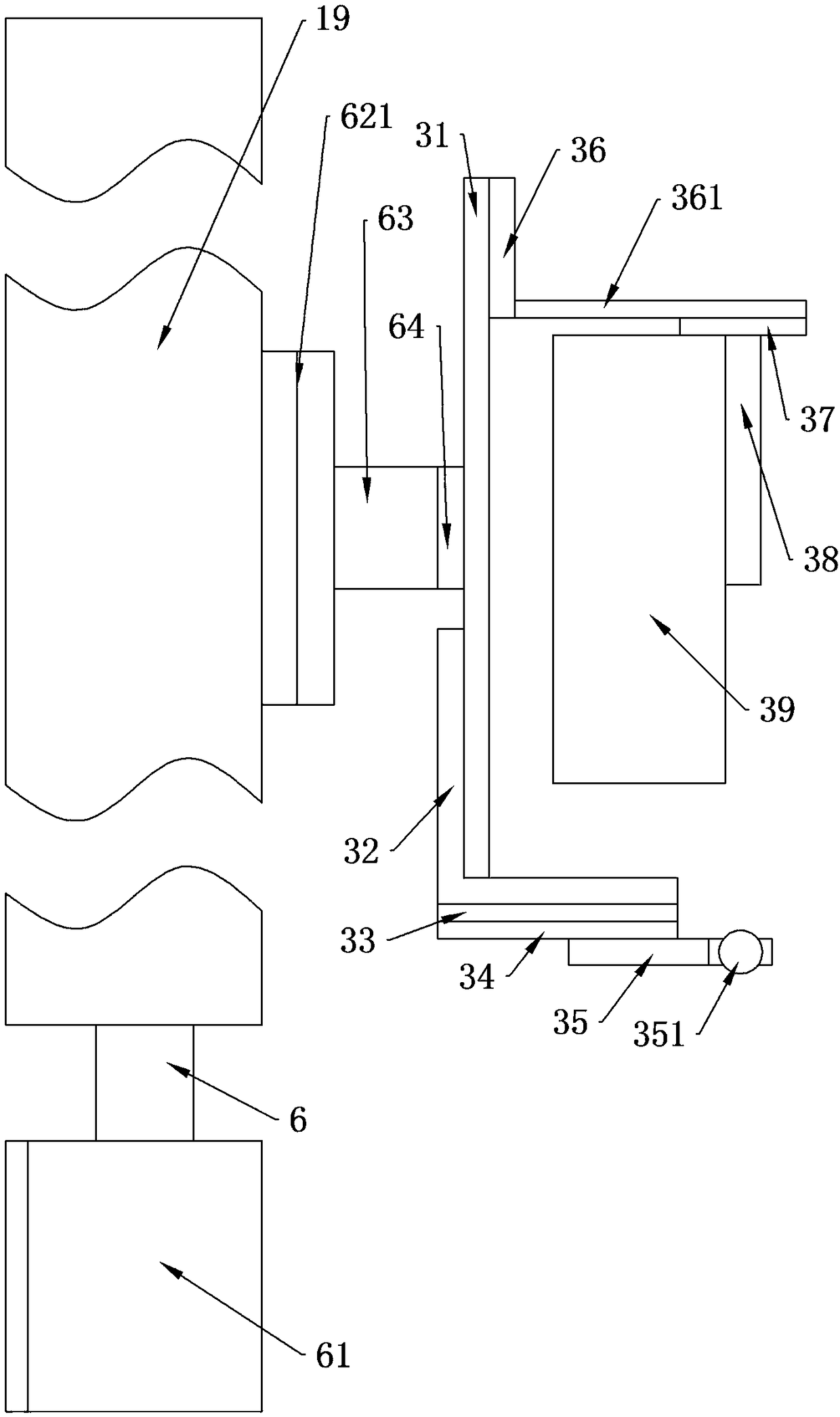
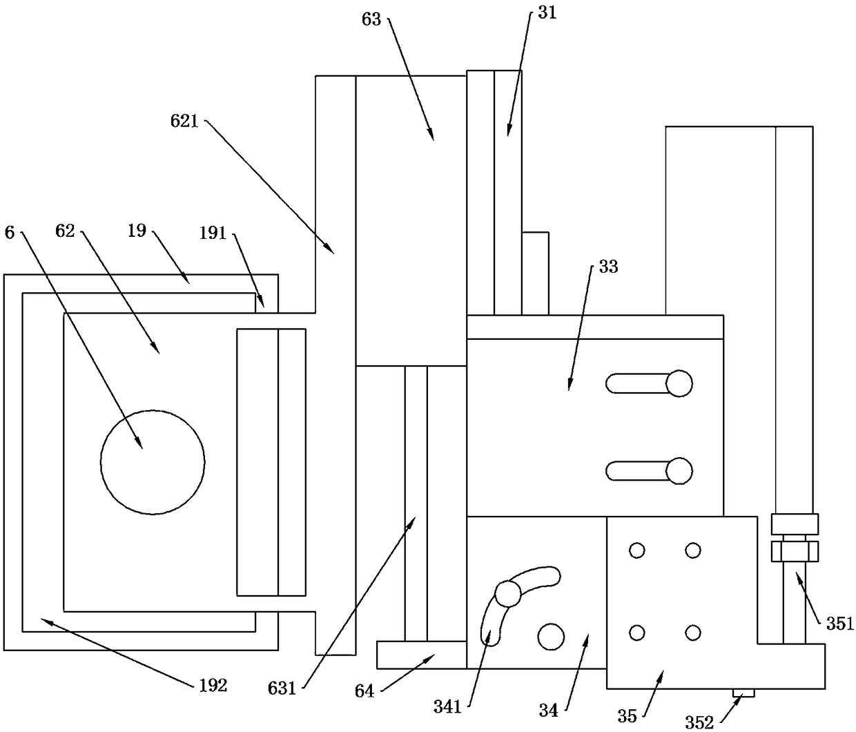
[0043] The specific embodiment of the present invention sees Figure 1-14 :

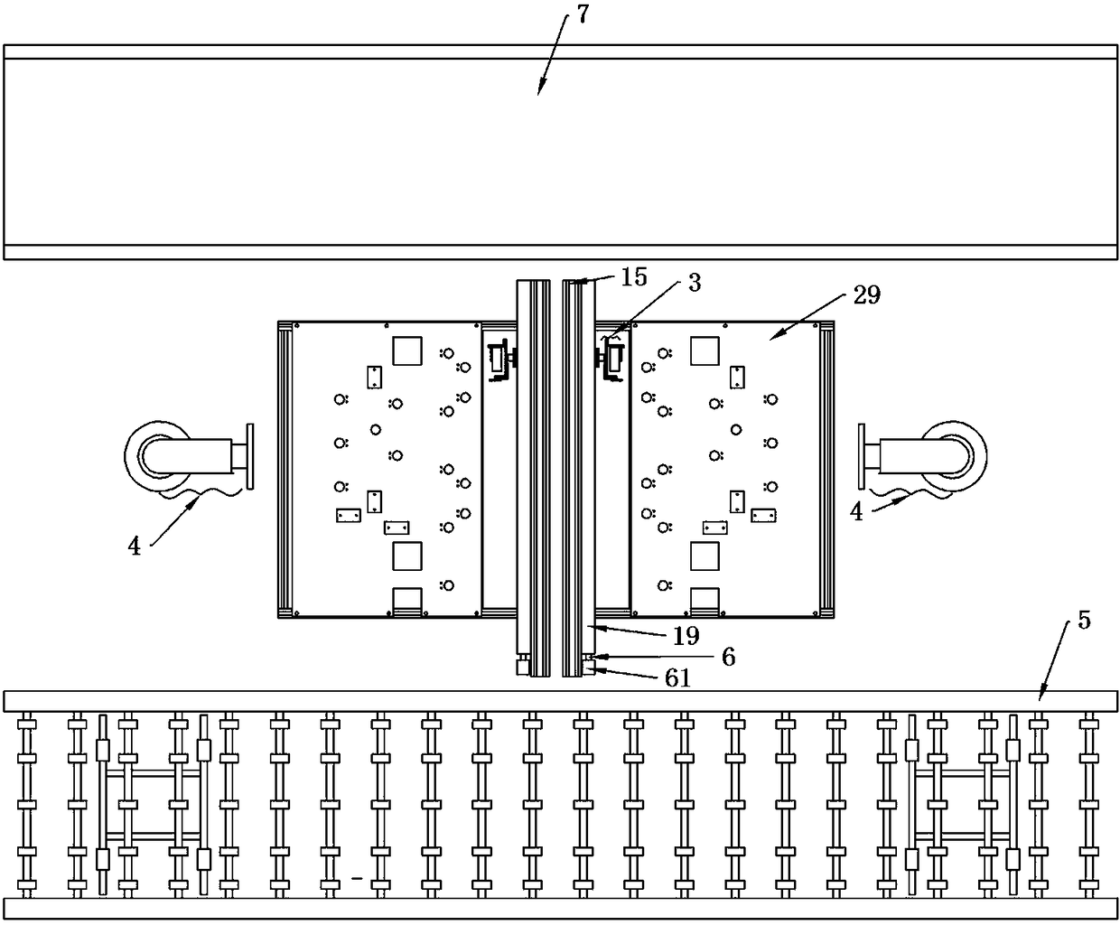
[0044] An automatic dispensing production line with single-line delivery, such as Figure 1-3 , including two dispensing devices facing away from each other and horizontally side by side, a handling robot 4 is arranged on the left side of the dispensing device on the left side, and a handling robot 4 is also arranged on the right side of the dispensing device on the right side, and the two handling robots The front of the robot 4 is provided with a horizontally arranged feeding conveyor 5, and the rear is provided with a horizontally arranged blanking conveyor belt 7. The feeding conveyor 5 is provided with a plurality of evenly distributed rotating shafts 51 driven by chains. A plurality of evenly distributed rollers 52 are fixed on the rotating shaft 51, and the two side ends of the feeding conveyor frame 5 are provided with lifting frames 8 located below, and the lifting frames 8 include horizont...


PUM


Abstract

The invention discloses a single line conveying automatic glue dispensing production line. On the single line conveying automatic glue dispensing production line, glass plates on a loading conveying frame are continuously conveyed from the right to the left; when the first glass plate is conveyed to the position of a lifting frame on the right side, the lifting frame rises under the driving of a hydraulic cylinder, the lifting frame lifts the glass plate, and a conveying robot on the right side takes out the glass plate on the lifting frame and transfers the glass plate to a glue dispensing carrying platform to be coated with glue; rectangular frames extending outside are arranged at the middle parts of vertical rods above U-shaped frames; the internal sides of the rectangular frames are open; the two rectangular frames are oppositely arranged to form a glass plate passage; when the lifting frame on the right side lifts upwards, the glass plate can pass through the glass plate passagewithout affecting the conveying of the glass plate; and a lifting frame on the left side rises when the glass plate reaches a position above the lifting frame on the left side. The two conveying robots alternately work so that the working efficiency is high.

Description

technical field [0001] The invention relates to the technical field of automatic glue dispensing, in particular to an automatic glue dispensing production line with single-line conveyance. Background technique [0002] In the production process of the LCD screen, the side of the glass plate needs to be coated with glue. The traditional glue coating method will lay the glass plate flat, and the glue will flow down due to the influence of gravity, and it is easy to apply uneven glue. Another extreme method is adopted. The glass plate is placed vertically, and the glue will not be affected by gravity at all, but the glass plate is not easy to install and fix. For example, the Chinese invention patent with application number 2017201052197 discloses a OLED side glue curing system, and the glass substrate is not easy to install and fix. , and use the rotating shaft to adjust the position of the stage, the positioning is not reliable; and the glue itself is sticky, it does not need...

Claims


Application Information

Patent Timeline
IPC IPC(8): B05C5/02B05C13/02B05D3/02
CPCB05C5/027B05C13/02B05D3/0254
Inventor 郑智仁祁原朋
Owner 河南天扬光电科技有限公司
Learn More