Fixture, test device and test method for pacemaker in vitro test
A technology for in vitro testing and fixing devices, applied in the fields of electrotherapy, cardiac stimulator, therapy, etc., can solve problems such as affecting the accuracy of test results, and achieve the effect of facilitating the replacement and connection of pacemakers, eliminating the impact and improving the accuracy
- Summary
- Abstract
- Description
- Claims
- Application Information
AI Technical Summary
Problems solved by technology
Method used
Image
Examples
Embodiment 1
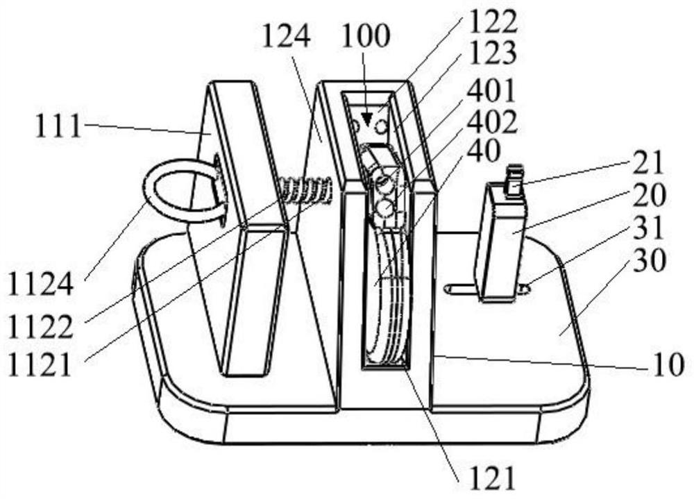
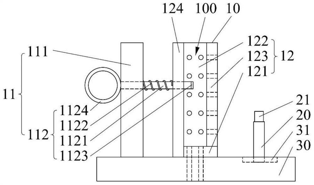
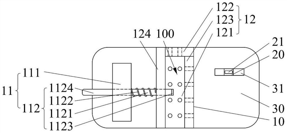
[0057] Please refer to Figure 1 to Figure 3 , figure 1 It is a perspective view of the use state of the fixation device for in vitro testing of the pacemaker in Embodiment 1 of the present invention, figure 2 It is the front view of the fixture device for in vitro testing of the pacemaker according to Embodiment 1 of the present invention, image 3 yes figure 2 Top view of the fixture shown.
[0058] Such as Figure 1 to Figure 3 As shown, the present embodiment provides a fixing device for in vitro testing of pacemakers, the fixing device includes a base 30 and a first fixing part 10 disposed on the base 30, and the first fixing part 10 defines an accommodation space 100 , which can be used to accommodate a pacemaker 40, and the first fixing part 10 can be locked with the pacemaker 40, that is, the first fixing part 10 can limit the direction and position of the pacemaker 40 . When testing the pacemaker 40, the pacemaker 40 is locked on the fixing device, and the ele...
Embodiment 2
[0099] Please refer to Figure 8 and Figure 9 , Figure 8 It is the front view of the fixture device for in vitro testing of the pacemaker according to the second embodiment of the present invention, Figure 9 yes Figure 8 Top view of the fixture shown.
[0100] The difference from the first embodiment is that the first fixing part 11 of this embodiment only has the fixing body 111 without the supporting body 124 , and only the third side wall 123 has a porous structure. Preferably, any two of the first side wall 121 , the second side wall 122 and the third side wall 123 are arranged on the same side and are perpendicular to each other.
[0101] Here, because the first fixing part 11 does not have a support body 124, the accommodating space 100 of the first limiting part 12 has a higher degree of opening than that of the first embodiment. When any side wall of a limiting part 12 is attached, most of the simulated fluid in vitro can be discharged through the open area of...
Embodiment 3
[0106] Please refer to Figure 10 and Figure 11 , Figure 10 is the front view of the fixture device for in vitro testing of the pacemaker according to Embodiment 3 of the present invention, Figure 11 yes Figure 10 Top view of the fixture shown.
[0107] The difference from the first embodiment is that the first fixing part 11 of this embodiment only has the fixing body 111 without the supporting body 124 , and only the second side wall 122 and the third side wall 123 are porous structures. Preferably, any two of the first side wall 121 , the second side wall 122 and the third side wall 123 are arranged on the same side and are perpendicular to each other.
[0108] In addition, in this embodiment, the fixing body 111 is preferably disposed parallel to the third side wall 123 , and is perpendicular to and connected to the first side wall 121 and the second side wall 122 respectively. The locking body 112 is preferably an elastic piece, one end of which is connected to t...
PUM
 Abstract
Description
Claims
Application Information
 - R&D
- Intellectual Property
- Life Sciences
- Materials
- Tech Scout
- Unparalleled Data Quality
- Higher Quality Content
- 60% Fewer Hallucinations
Browse by: Latest US Patents, China's latest patents, Technical Efficacy Thesaurus, Application Domain, Technology Topic, Popular Technical Reports.
© 2025 PatSnap. All rights reserved.Legal|Privacy policy|Modern Slavery Act Transparency Statement|Sitemap|About US| Contact US: help@patsnap.com


