
Vertical injection molding machine for production of electronic accessories

A technology for injection molding machines and accessories, applied in the field of vertical injection molding machines for the production of electronic accessories, can solve problems such as hidden health hazards, bulky, precipitation and solidification of operators, improve fixing effect, improve structural stability, and avoid manual operation. the dangerous effect of

Inactive Publication Date: 2018-12-14
连云港久鑫电子有限公司
View PDF4 Cites 4 Cited by
  • Summary
  • Abstract
  • Description
  • Claims
  • Application Information

AI Technical Summary

Problems solved by technology

[0003] In the production process of electronic accessories, due to the small structure of electronic accessories, injection molding machines can be used to quickly manufacture them. The vertical injection molding machines in the prior art have complex structures and large volumes. After the injection molding is completed, they lack the function of ejecting materials and require operation. Personnel take the injection molded parts manually, which makes the whole process dangerous to a certain extent. Moreover, during the process of heating and melting the plastic, a large amount of smoke will be emitted, and the smoke will float into the air, which will cause harm to the health of the operators. At the same time, the vertical injection molding machine in the prior art will have a certain viscosity after the plastic is melted. When used for a long time, precipitation and solidification will occur. Therefore, a vertical injection molding machine for electronic accessories is designed. machine is necessary

Method used


Image

  • Vertical injection molding machine for production of electronic accessories
  • Vertical injection molding machine for production of electronic accessories
  • Vertical injection molding machine for production of electronic accessories

Examples


Embodiment Construction

[0023] The following will clearly and completely describe the technical solutions in the embodiments of the present invention with reference to the accompanying drawings in the embodiments of the present invention. Obviously, the described embodiments are only some, not all, embodiments of the present invention. Based on the embodiments of the present invention, all other embodiments obtained by persons of ordinary skill in the art without making creative efforts belong to the protection scope of the present invention.

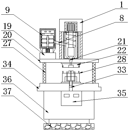
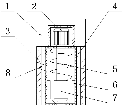
[0024] see Figure 1-6, the present invention provides a technical solution: a vertical injection molding machine for electronic accessories, including a drive box 1, an injection motor 2, a bracket 3, an injection cylinder 4, a screw rod 5, a discharge trough 6, a tapered column 7, Feeding pipe 8, hopper 9, air cleaner 10, smoke removal hole 11, heating cylinder 12, heating coil 13, stirring shaft 14, stirring frame 15, connecting block 16, feeding port 17, s...


PUM


Abstract

The invention discloses a vertical injection molding machine for production of electronic accessories. The vertical injection molding machine comprises a driving box, an injection motor, a support, aninjection barrel, a screw rod, a discharging groove, a conical post, a conveying pipe, a hopper, an air purifier, a smoke removal hole, a heating barrel, a heating coil, a stirring shaft, a stirringrack, a connecting block, a conveying port, a stirring motor, a bottom plate, a top plate, an injection molding pipe, an upper mold seat, a first fixing plate, a dropping hole, an injection molding cavity, a mounting positioning hole, an electric telescopic rod, a lower mold seat, a second fixing plate, a discharging frame, a positioning pin, an accessory mold, a hydraulic rod, an operation table,a hydraulic station, a case, a support plate and an electric control box, wherein the electronic control box is mounted on one side of the case through bolts, the hydraulic station is mounted in thecase through bolts, and the operation table is mounted at the top of the case through bolts. The vertical injection molding machine can perform injection molding conveniently through upper and lower molds and has material ejection and air purification functions, and the convenience in use is greatly improved.

Description

technical field [0001] The invention relates to the technical field of vertical injection molding machines, in particular to a vertical injection molding machine for making electronic accessories. Background technique [0002] The vertical injection molding machine is a mechanical device; in a cycle of the injection molding machine, a certain amount of plastic can be heated and plasticized within a specified time, and the molten plastic can be injected into the mold through the screw under a certain pressure and speed. cavity. [0003] In the production process of electronic accessories, due to the small structure of electronic accessories, injection molding machines can be used to quickly manufacture them. The vertical injection molding machines in the prior art have complex structures and large volumes. After the injection molding is completed, they lack the function of ejecting materials and require operation. Personnel take the injection molded parts manually, which mak...

Claims


Application Information

Patent Timeline
Patent Type & Authority Applications(China)
IPC IPC(8): B29C45/03B29C45/17B29C45/26B29C45/40
CPCB29C45/03B29C45/17B29C45/2606B29C45/4005
Inventor 陆惠良
Owner 连云港久鑫电子有限公司
Learn More