Antenna beam search method and device
An antenna beam and search method technology, applied in diversity/multi-antenna systems, wireless communication, radio transmission systems, etc., can solve the problems of occupying system resources, affecting business performance, and time-consuming antenna beams, so as to improve work efficiency and reduce The effect of small business volume and shortened duration
- Summary
- Abstract
- Description
- Claims
- Application Information
AI Technical Summary
Problems solved by technology
Method used
Image
Examples
no. 1 example
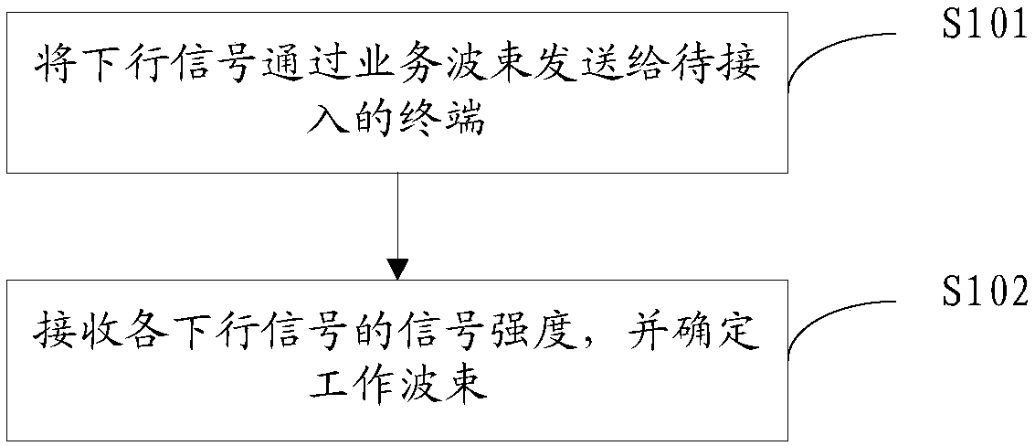
[0020] Please refer to figure 1 , figure 1 It is a flow chart of an antenna beam search method provided in the first embodiment of the present invention, including:
[0021] S101. The base station sends a downlink signal to a terminal to be accessed through an antenna beam;
[0022] S102. The base station receives the signal strength of each downlink signal fed back by the terminal, and uses a service beam meeting a preset condition as a working beam for terminal access.
[0023] An array antenna is an antenna system composed of many identical single antennas arranged according to certain rules, also known as an antenna array, and the independent unit commonly known as an antenna array is called an array element or an antenna unit. According to the arrangement of the array elements, when the array elements are arranged in a straight line, it is called a linear array; when the array elements are arranged in a plane, it is called a planar array. Antennas are widely used in ra...
no. 2 example
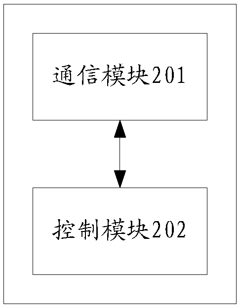
[0038] Please refer to figure 2 , figure 2 It is a schematic diagram of the composition of an antenna beam search device provided in the second embodiment of the present invention, including:
[0039] A communication module 201, configured to send a downlink signal to a terminal to be accessed through an antenna beam;
[0040] The communication module 201 is also used to: receive the signal strength of each downlink signal fed back by the terminal;
[0041] The control module 202 is configured to use a service beam satisfying a preset condition as a working beam accessed by a terminal.
[0042] Since the physical distance between the terminal and the base station is relatively long, and the distance between the array antennas included in the base station is much smaller than the distance between the terminal and the base station, then the direction of the antenna beam in one array antenna is different from that of other array antennas. The directions of the corresponding ...
no. 3 example
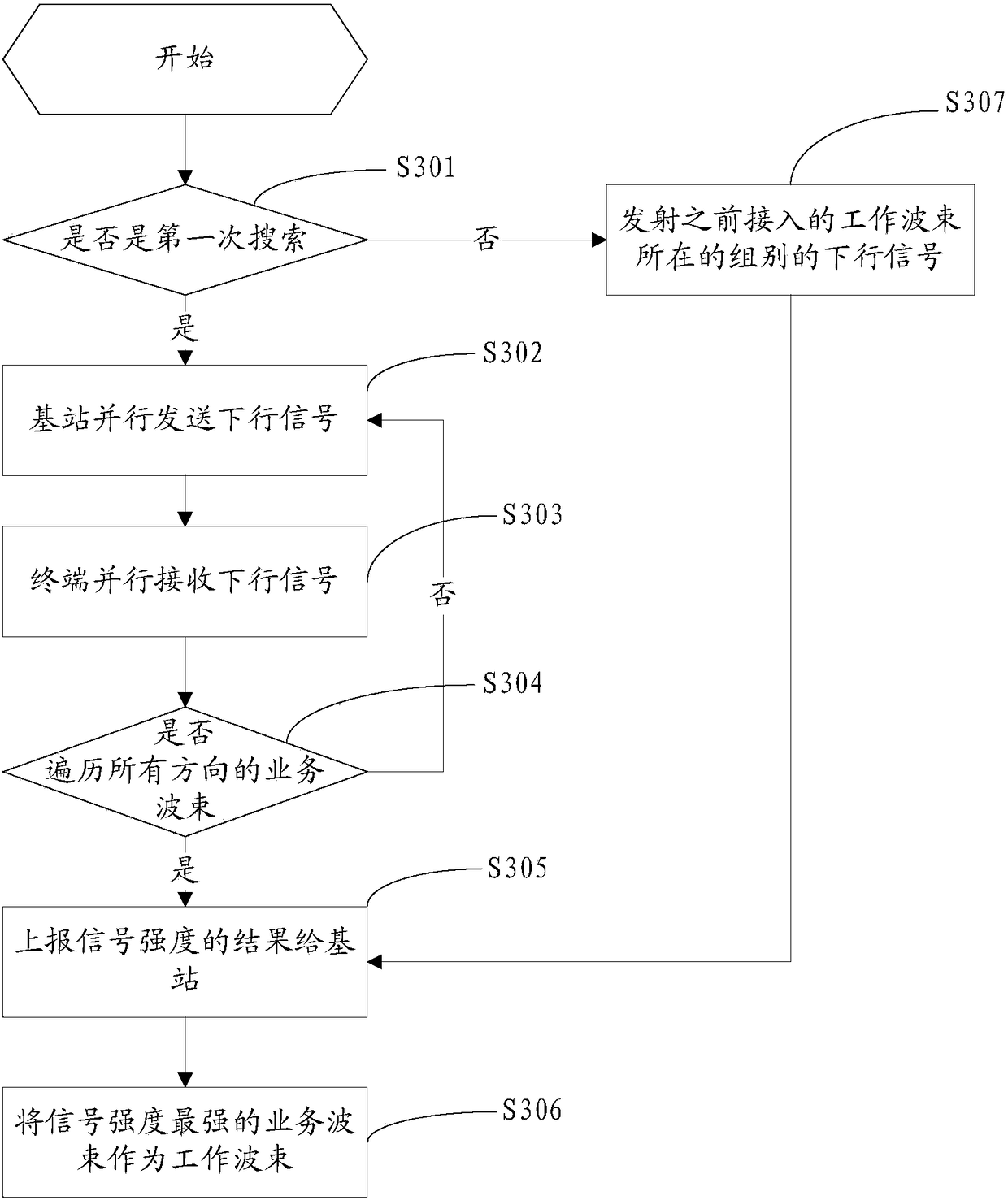
[0054] Please refer to image 3 , image 3 It is a flow chart of an antenna beam search method provided in the third embodiment of the present invention, including:
[0055] S301. Judging whether it is the first time to search for the service beam corresponding to the terminal to be accessed, if yes, go to S302; if not, go to S307;
[0056] When the terminal wants to search for a new round of working beams, it can refer to the previous service beams used by the terminal, because the moving speed of the terminal is generally slower than that of the base station, so the movement of the terminal generally does not exceed one Or the coverage of service beams in two adjacent directions. Therefore, by determining the working beam used by the terminal for the last access, the service beam required by the terminal can be located more quickly and the required time can be further shortened. .
[0057] S302, the base station sends T in parallel UE downlink signal;
[0058] The speci...
PUM
 Abstract
Description
Claims
Application Information
 - R&D
- Intellectual Property
- Life Sciences
- Materials
- Tech Scout
- Unparalleled Data Quality
- Higher Quality Content
- 60% Fewer Hallucinations
Browse by: Latest US Patents, China's latest patents, Technical Efficacy Thesaurus, Application Domain, Technology Topic, Popular Technical Reports.
© 2025 PatSnap. All rights reserved.Legal|Privacy policy|Modern Slavery Act Transparency Statement|Sitemap|About US| Contact US: help@patsnap.com


