Shift register circuit and display device

A technology of shift temporary storage and shift temporary storage unit, which is used in information storage, static memory, static indicator, etc.

Active Publication Date: 2021-07-23
HKC CORP LTD
View PDF5 Cites 0 Cited by
  • Summary
  • Abstract
  • Description
  • Claims
  • Application Information

AI Technical Summary

Problems solved by technology

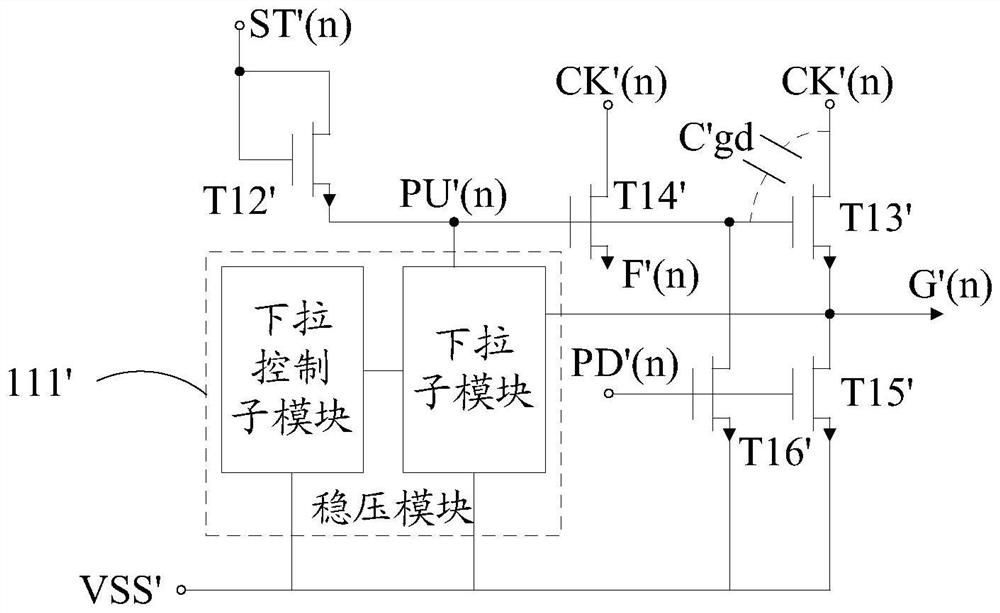
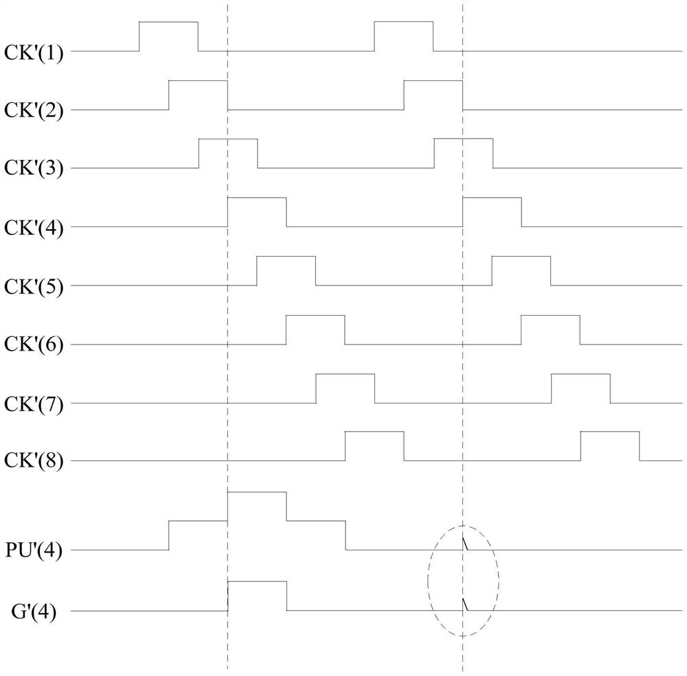
[0003] The main purpose of the present invention is to propose a shift temporary storage circuit, which aims to solve the technical problem of timing noise in the above-mentioned display device and improve the display effect of the display device

Method used


Image

  • Shift register circuit and display device
  • Shift register circuit and display device
  • Shift register circuit and display device

Examples


Embodiment Construction

[0023] The following will clearly and completely describe the technical solutions in the embodiments of the present invention with reference to the accompanying drawings in the embodiments of the present invention. Obviously, the described embodiments are only part of the embodiments of the present invention, not all of them. Based on the embodiments of the present invention, all other embodiments obtained by persons of ordinary skill in the art without creative efforts fall within the protection scope of the present invention.

[0024] It should be noted that if there is a directional indication (such as up, down, left, right, front, back...) in the embodiment of the present invention, the directional indication is only used to explain the position in a certain posture (as shown in the accompanying drawing). If the specific posture changes, the directional indication will also change accordingly.

[0025] In addition, if there are descriptions involving "first", "second" and ...


PUM


Abstract

The invention discloses a shift temporary storage circuit and a display device. The shift temporary storage circuit includes a cascaded multi-stage shift temporary storage unit. The shift temporary storage unit includes a charging module, an output module, a reset module and a voltage stabilizing module. The voltage stabilizing module includes a first voltage stabilizing sub-module and a second voltage stabilizing sub-module. In the voltage stabilizing sub-module, the first ends of the first voltage stabilizing sub-module and the second voltage stabilizing sub-module are electrically connected to the low-frequency voltage stabilizing signal source and the high-frequency voltage stabilizing signal source respectively, and the second ends are respectively connected to the shift temporary storage of the current stage. The scanning signal output end of the unit is electrically connected, the third end is electrically connected to the pull-up point of the shift temporary storage unit of the current stage, and the fourth end is electrically connected to the low-level signal source respectively. When the low-frequency voltage stabilization signal is at a high level, The first voltage stabilizing sub-module is connected to the pull-up point, the scanning signal output terminal and the low-level signal source. Flat signal source. The technical scheme of the invention can eliminate timing noise.

Description

technical field [0001] The invention relates to the field of display technology, in particular to a shift register circuit and a display device. Background technique [0002] In a traditional display device, the row scanning signal is realized by an external integrated circuit. With the development of thinner and lighter display devices, narrower borders and lower costs, gate drive integration (Gate Drive on Array, GOA) realizes the output of the row scanning signal, specifically by integrating the shift register circuit on the array substrate of the display device. However, since in the multi-clock shift register circuit, the clock signal is a periodic signal, and the same clock signal often controls multiple shift register units in the shift register circuit, resulting in timing noise, which further affects the display The display of the device is causing adverse effects. Contents of the invention [0003] The main purpose of the present invention is to provide a shift...

Claims


Application Information

Patent Timeline
Patent Type & Authority Patents(China)
IPC IPC(8): G09G3/20G09G3/36G11C19/28
CPCG09G3/20G09G3/3611G09G3/3696G09G2310/0286G11C19/28
Inventor 何怀亮
Owner HKC CORP LTD
Why Eureka
Try Eureka