
Tandem-type thermostat device of internal combustion engine

An internal combustion engine, tandem technology, used in mechanical equipment, engine components, machines/engines, etc., can solve problems such as increasing fuel consumption and environmental pollution, accelerating cold wear of internal combustion engines, and unstable working temperature, achieving small changes and water temperature. Fast, easy-to-implement effects

Pending Publication Date: 2018-12-11
陈俊含
View PDF0 Cites 0 Cited by
  • Summary
  • Abstract
  • Description
  • Claims
  • Application Information

AI Technical Summary

Problems solved by technology

[0004] The existing internal combustion engine thermostat setting has the disadvantages of long warm-up time or unstable working temperature
This greatly increases fuel consumption and environmental pollution, and accelerates the cold wear of the internal combustion engine

Method used


Image

  • Tandem-type thermostat device of internal combustion engine
  • Tandem-type thermostat device of internal combustion engine

Examples


Embodiment 1

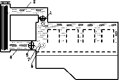
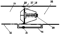
[0016] A temperature-saving device for a tandem internal combustion engine includes a thermostat 1 for an outlet pipe and a thermostat 5 for a return pipe. For most of the internal combustion engines where the original thermostat is set at the return pipe 4, the newly installed thermostat should be installed near the end of the internal combustion engine at the outlet pipe 2. In this type of internal combustion engine, the water outlet pipe thermostat 1 is newly installed thermostat 1. The water inlet 11 of the newly installed thermostat 1 is connected with the water outlet 8 of the internal combustion engine by a rubber bushing, and the water outlet 15 is connected with the water inlet 9 of the radiator 3 by the water outlet pipe 2 . On the water inlet 11 and the water outlet 15 of the newly installed thermostat 1, there is a bypass pipe 14 with an inner diameter greater than 3 mm, and the bypass pipe 14 is provided with a bypass valve switch 13 . When adding or replacing th...

Embodiment 2

[0018] For the small number of internal combustion engines where the original thermostat is installed at the water outlet pipe 2, the newly installed economizer should be installed near the internal combustion engine end at the internal combustion engine return water pipe 4. In this type of internal combustion engine, the return water pipe thermostat 5 is newly installed thermostat 5. The newly installed section 5 water outlet 15 is connected with the water inlet 7 of the internal combustion engine by a rubber sleeve, and the water inlet 11 is connected with the water outlet 10 of the radiator 3 by the return pipe 4 .

Embodiment 3

[0020] According to the needs of the cooling system layout or the limitation of the installation location, the newly installed thermostat can be installed not only at the end near the internal combustion engine, but also at any position near the end of the radiator 3 or on the outlet pipe 2 and return pipe 4. Can be installed inside the internal combustion engine, radiator (3).


PUM


Abstract

The invention discloses a tandem-type thermostat device of an internal combustion engine. The tandem-type thermostat device comprises a water return pipe thermostat and a water outlet pipe thermostat.At the cold state, main valves of the two thermostats are both in a closed state, and cooling liquid is firmly locked in a limited space of the internal combustion engine to be rapidly heated; when the cooling liquid in the internal combustion engine rapidly reaches a certain temperature, the main valve of the water outlet pipe thermostat is opened, and the cooling liquid in the internal combustion engine and the cooling liquid in a radiator conduct trace heat exchange; and with opening and closing of the main valve of the water outlet pipe thermostat, the cooling liquid in the radiator is heated alternately and gradually, when the temperature of the cooling liquid is increased to the certain temperature, the main valve of the water return pipe thermostat is opened, a cooling system is connected, and the cooling liquid achieving heat balance flows back to the internal combustion engine. Through the design of the tandem-type thermostats, the warm-up speed of the internal combustion engine can be higher, the working temperature is steadier, the energy efficiency is higher, and the tandem-type thermostat device is friendlier to the environment.

Description

technical field [0001] The invention relates to a thermostat for an internal combustion engine cooling system, in particular to a thermostat for an internal combustion engine. Background technique [0002] The existing water-cooled internal combustion engine cooling system has only one thermostat (excluding the case where a few large diesel engines use two thermostats connected in parallel to increase the coolant flow), and most of them are installed at the return pipe of the internal combustion engine. Although this design can make the working temperature of the internal combustion engine relatively stable, the coolant in the internal combustion engine and the radiator is not effectively isolated at the water outlet pipe. When the internal combustion engine is running, the coolant in the internal combustion engine and the radiator are heated at the same time, consuming a lot of heat , slowing down the warm-up speed of the internal combustion engine. Especially in the extre...

Claims


Application Information

Patent Timeline
IPC IPC(8): F01P7/16
CPCF01P7/16F01P2007/146
Inventor 陈俊含
Owner 陈俊含
Learn More