
Continuous self-cleaning oil-water separation device

An oil-water separation device and self-cleaning technology, applied in separation methods, liquid separation, grease/oily substance/float removal devices, etc., can solve the problems of large geometric volume, low separation accuracy, and complicated manufacturing, and achieve the geometric volume of the device. Small, low separation energy consumption, the effect of reducing the possibility

Pending Publication Date: 2018-12-11
BEIJING UNIV OF CHEM TECH
View PDF3 Cites 1 Cited by
  • Summary
  • Abstract
  • Description
  • Claims
  • Application Information

AI Technical Summary

Problems solved by technology

[0003] In view of the above problems, the present invention proposes a continuous self-cleaning oil-water separation device, which adopts a coating material with a certain thickness and a certain strength on the outside of the stainless steel mesh, and the stainless steel mesh has a built-in external diameter gradient combined rotor, and is connected with an external multi-stage The combination method of structural adsorption cotton connects, breaks through the shortcomings of existing oil-water separation devices such as complex design and manufacture, large geometric volume, high cost, low separation accuracy, and the need to stop for maintenance and cleaning, and realize continuous self-cleaning oil-water separation

Method used


Image

  • Continuous self-cleaning oil-water separation device
  • Continuous self-cleaning oil-water separation device
  • Continuous self-cleaning oil-water separation device

Examples


Embodiment Construction

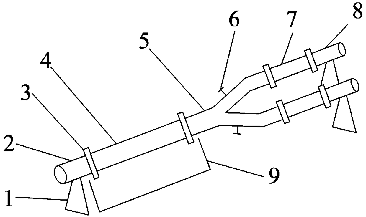
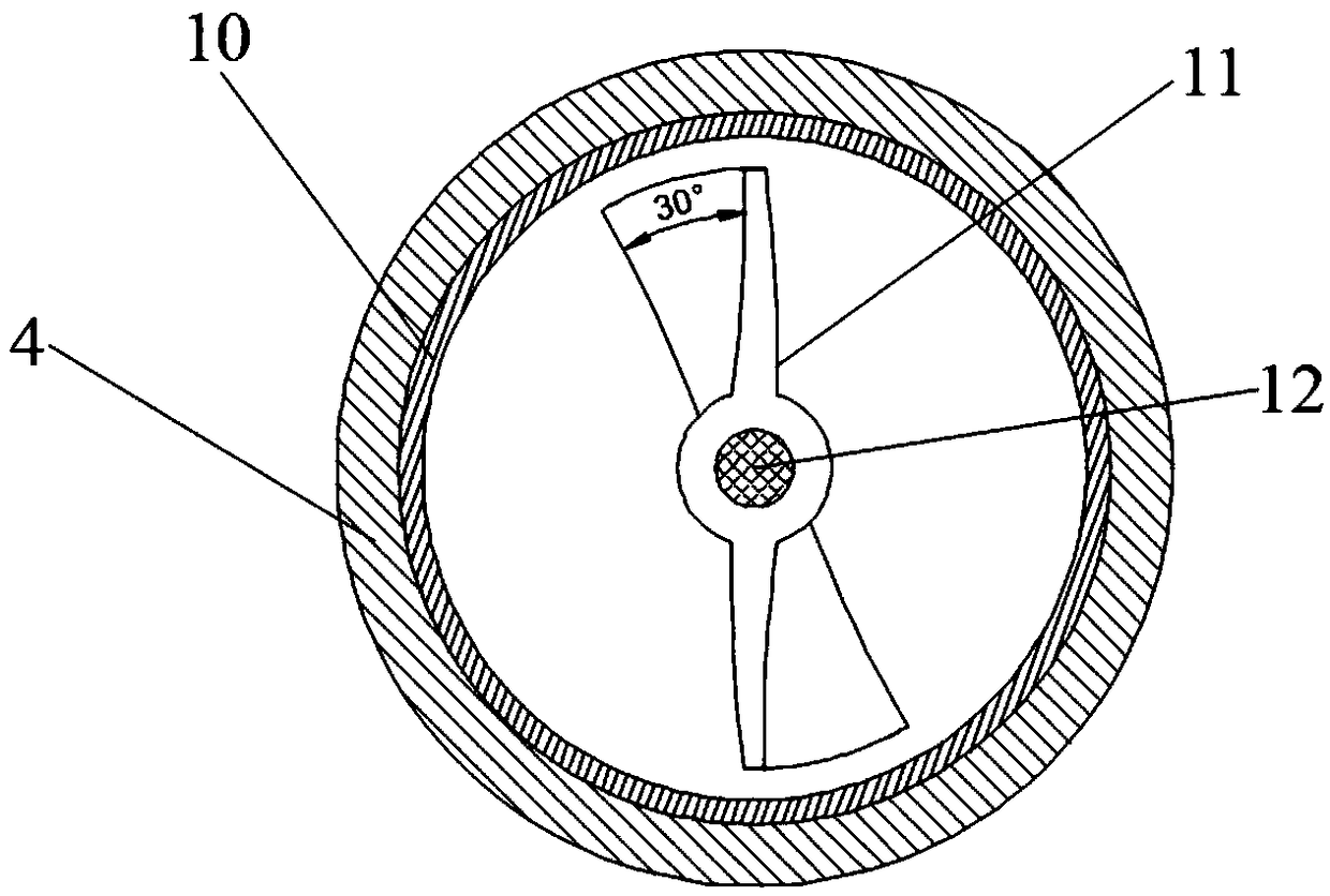
[0025] A high-efficiency continuous self-cleaning oil-water separation device of the present invention mainly includes a bracket 1, a liquid inlet pipe 2, a flange 3, a coating material 4, a shunt pipe 5, a valve 6, a multi-stage structure absorbent cotton 7, a liquid discharge pipe 8, Separation liquid collection box 9, stainless steel mesh 10, fluid-driven rotor 11, steel wire rope 12, position sensor 13, controller 14, electromagnetic limit device 16, and fixture 15, such as figure 1 and figure 2 shown. The stainless steel mesh 10 is connected with the liquid inlet pipe 2 and the shunt pipe 5 through the flange 3, and the stainless steel mesh 10 is coated with a certain thickness and a cladding material 4 with a certain strength, and a separating liquid collection box 9 is placed below, and two shunt pipes 5 ( or multiple) branch pipes are equipped with valves 6 respectively, and the multi-stage structure absorbent cotton 7 is connected with the shunt pipe branch pipe and...


PUM


Abstract

The invention discloses a continuous self-cleaning oil-water separation device. The device is mainly composed of a supporting frame, a liquid inlet pipe, flanges, a coating material, a flow dividing pipe, a valve, multi-stage structure absorption cotton, a liquid draining pipe, a separation liquid collecting box, a stainless steel net, a fluid driving rotor, a steel wire rope, a position sensor, acontroller, an electromagnetic limiting device and a fixing piece. The stainless steel net is produced to be barrel-shaped to be matched with the flanges, the two ends of the stainless steel net arewelded with the flanges and connected with the liquid inlet pipe and the flow dividing pipe respectively, the outside of the stainless steel net is coated with the coating material with the certain thickness and the certain strength, the separation liquid collecting box is placed on the lower face, and the fluid driving rotor is arranged in the stainless steel net. The device achieves self-cleaning by internally arranging the fluid driving rotor, the separation precision is improved through secondary separation conducted by the rear-arranged multi-stage structure absorption cotton, macroporesat the front end can further contain impurity particles in the oil-water separation liquid, the separation liquid is purified particularly, the post-treatment difficulty of the separation liquid is simplified, and the service life of the absorption cotton is prolonged.

Description

technical field [0001] The invention relates to a continuous self-cleaning oil-water separation device, which belongs to the field of oil-water separation. Background technique [0002] In the petrochemical and environmental protection fields, oil-water separation devices are important production equipment, and oil-water separation technology is crucial to industry development and environmental protection. At present, there are many kinds of oil-water separation devices, which are widely used in the treatment of oily wastewater from oil fields and natural gas production, oily wastewater from oil depots, and other industrial oily wastewater. Gravity oil-water separation device is a commonly used process equipment in production, but due to design limitations, the existing separation device has serious short-circuit flow, large power consumption, high energy consumption, complex internal structure, and large geometric volume. High manufacturing cost; because industrial oily wa...

Claims


Application Information

Patent Timeline
Patent Type & Authority Applications(China)
IPC IPC(8): C02F1/40B01D17/022C02F103/10
CPCB01D17/0202C02F1/40C02F2103/10
Inventor 杨卫民曹如楼阎华李好义陈明军左夏华丁秦丁玉梅
Owner BEIJING UNIV OF CHEM TECH
Learn More