
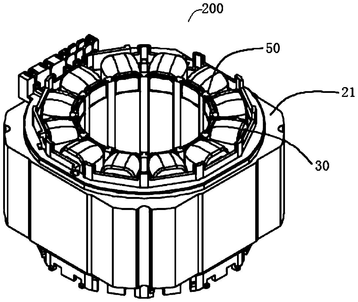
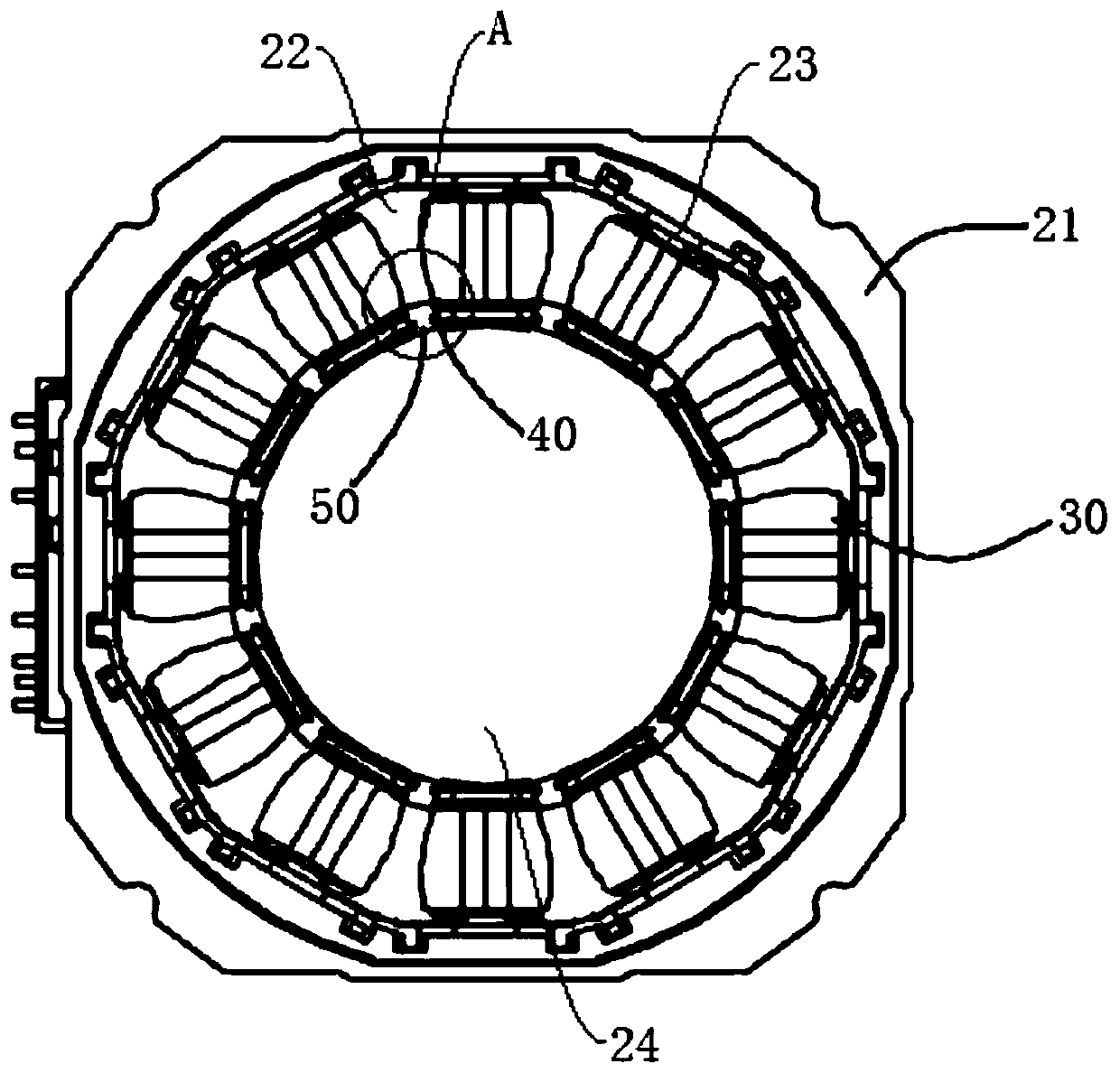
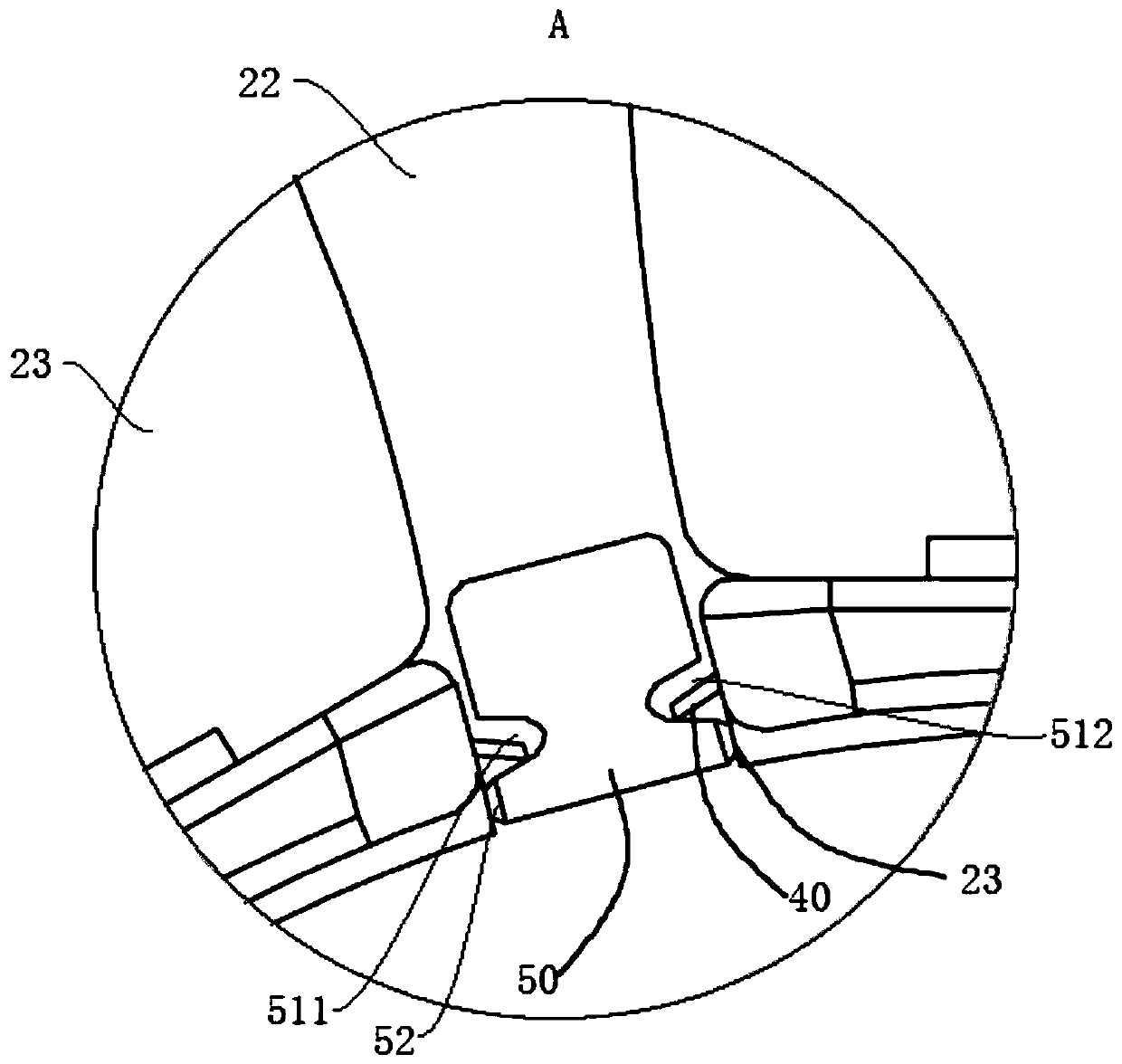
Washing machine, washing machine motor and its stator assembly

A technology for washing machines and motors, applied to the shape/style/structure of winding insulation, which can solve problems such as motor overcurrent, phase-to-phase short circuit, fire hazards, etc., and achieve the effects of reducing noise, avoiding wind noise, and preventing accidents

Active Publication Date: 2020-04-14
WUXI LITTLE SWAN ELECTRIC CO LTD
View PDF7 Cites 0 Cited by
  • Summary
  • Abstract
  • Description
  • Claims
  • Application Information

AI Technical Summary

Problems solved by technology

[0002] In the prior art, the insulation structure of the brushless DC motor is composed of an upper insulating frame, a lower insulating frame and slot paper. The upper insulating frame and the lower insulating frame are installed at both ends of the stator core through positioning holes, and can only serve as coil ends. The role of insulation; the slot paper is installed in the stator slot to play the role of insulation between the stator slot and the coil, and there is no other insulation structure between the slots of the stator slot. When the motor rotates at high speed, the high-speed airflow generated by the rotation of the motor rotor will enter Between the notch of the stator slot and the gap between the two-layer coils of the same stator slot, wind noise is formed, which makes the motor generate noise, and the distance between the two-layer coils in the same stator slot near the slot is relatively close. When the motor is in a bad environment Or when the air is humid, it is easy to short circuit between phases, resulting in overcurrent of the motor and a fire hazard. Therefore, there is room for improvement

Method used


Image

  • Washing machine, washing machine motor and its stator assembly
  • Washing machine, washing machine motor and its stator assembly
  • Washing machine, washing machine motor and its stator assembly

Examples


Embodiment Construction

[0032] Embodiments of the present invention are described in detail below, examples of which are shown in the drawings, wherein the same or similar reference numerals designate the same or similar elements or elements having the same or similar functions throughout. The embodiments described below by referring to the figures are exemplary only for explaining the present invention and should not be construed as limiting the present invention.

[0033] In describing the present invention, it should be understood that the terms "center", "longitudinal", "transverse", "length", "width", "thickness", "upper", "lower", "front", " Back", "Left", "Right", "Vertical", "Horizontal", "Top", "Bottom", "Inner", "Outer", "Clockwise", "Counterclockwise", "Axial" , "radial", "circumferential" and other indicated orientations or positional relationships are based on the orientations or positional relationships shown in the drawings, which are only for the convenience of describing the present ...


PUM


Abstract

The invention discloses a washing machine, a motor for a washing machine and a stator assembly thereof. The stator assembly includes a stator core. The stator core has a plurality of stator teeth and a plurality of stator slots. The plurality of stator teeth are spaced along the circumferential direction of the stator core. arrangement, a stator slot is defined between two adjacent stator teeth; a stator winding, the stator winding is wound on a plurality of stator teeth; a plurality of insulating slot papers, the plurality of insulating slot papers are arranged on the plurality of stator slots in one-to-one correspondence, Each insulating slot paper is located between the stator teeth and the stator winding; at least one insulating insert is provided at the slot of the stator slot for closing at least part of the slot, and the side of the insulating insert facing the stator teeth has a concave Groove, a part of the insulating groove paper is located between the stator teeth and the insulating insert and is located in the groove. The stator assembly of a washing machine motor according to an embodiment of the present invention avoids wind noise caused by the rotation of the motor rotor, improves safety performance, has a simple structure, is easy to manufacture, and has a good user experience.

Description

technical field [0001] The invention relates to the field of clothes processing equipment, in particular to a washing machine, a washing machine motor and a stator assembly thereof. Background technique [0002] In the prior art, the insulation structure of the brushless DC motor is composed of an upper insulating frame, a lower insulating frame and slot paper. The upper insulating frame and the lower insulating frame are installed at both ends of the stator core through positioning holes, and can only serve as coil ends. The role of insulation; the slot paper is installed in the stator slot to play the role of insulation between the stator slot and the coil, and there is no other insulation structure between the slots of the stator slot. When the motor rotates at high speed, the high-speed airflow generated by the rotation of the motor rotor will enter Between the notch of the stator slot and the gap between the two-layer coils of the same stator slot, wind noise is formed,...

Claims


Application Information

Patent Timeline
Patent Type & Authority Patents(China)
IPC IPC(8): H02K3/38H02K3/32
CPCH02K3/32H02K3/38
Inventor 王永威胡明张小文
Owner WUXI LITTLE SWAN ELECTRIC CO LTD
Learn More