
Cable identification device

A cable installation and identification technology, applied in the direction of cable laying equipment, etc., can solve the problems of power failure and intact cables, damage, etc., and achieve the effect of reducing workload and improving work efficiency

Inactive Publication Date: 2018-12-07
HEFEI XINGLIAN COMM
View PDF5 Cites 5 Cited by
  • Summary
  • Abstract
  • Description
  • Claims
  • Application Information

AI Technical Summary

Problems solved by technology

Cause a large-scale blackout and may destroy intact cables

Method used


Image

  • Cable identification device
  • Cable identification device
  • Cable identification device

Examples


Embodiment Construction

[0018] In order to have a further understanding and understanding of the structural features of the present invention and the achieved effects, the preferred embodiments and accompanying drawings are used for a detailed description, as follows:

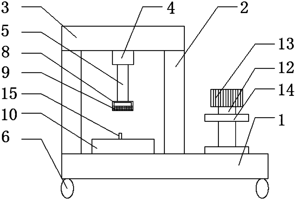
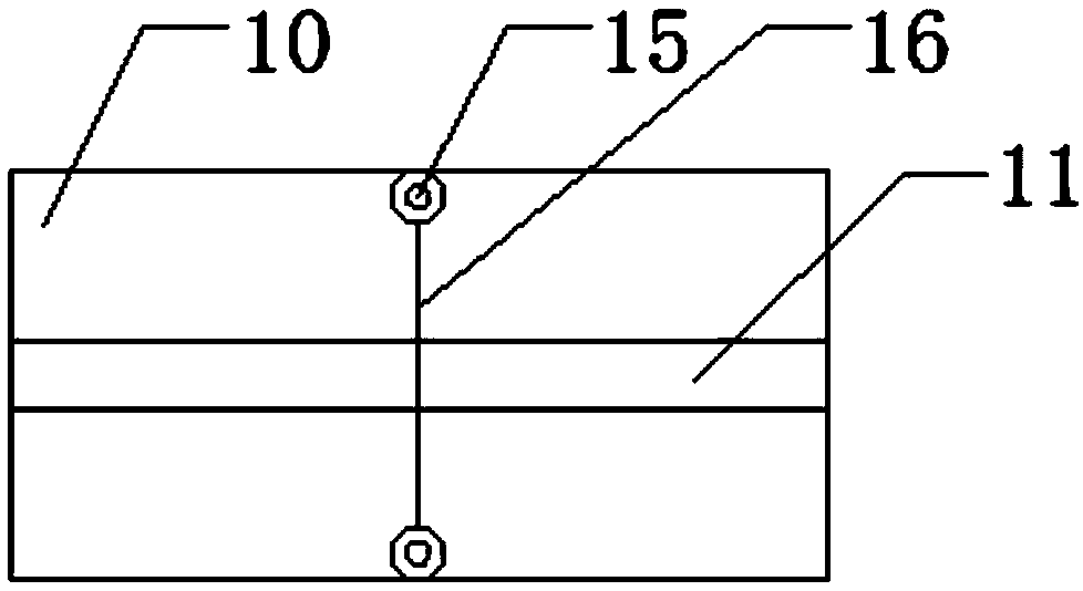
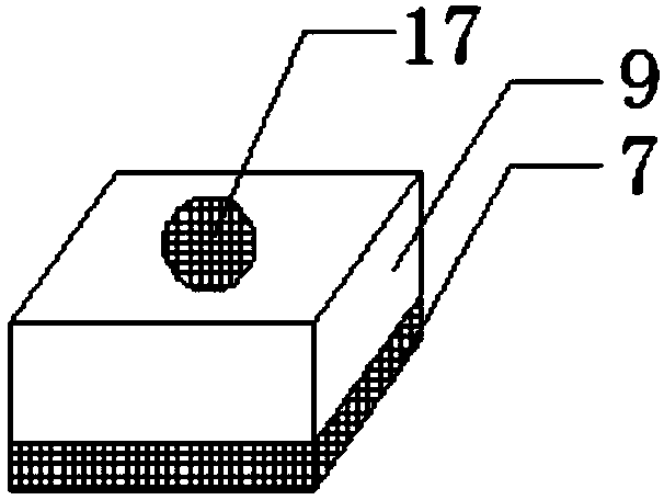
[0019] Refer to attached Figure 1-3 As shown, an identification cable device includes a base 1, a column 2, a top plate 3, a stamping mechanism and a wire take-up mechanism. The stamping mechanism includes a stamping cylinder 4 and a telescopic shaft 5. There are four above the base 1 Column 2, above the column 2 is provided with a top plate 3, the column 2 is located at the four corners below the top plate 3, the center of the lower surface of the top plate 3 is embedded with a stamping cylinder 4, the stamping cylinder The lower end of the telescopic shaft 5 at the end of 4 is provided with an annular groove 8, the bottom of the annular groove 8 is provided with a logo sticker 9, and the top of the base 1 is also provided with a bo...


PUM


Abstract

The invention discloses a cable identification apparatus. The cable identification apparatus comprises a base, columns, a top plate, a punching mechanism and a wire take-up mechanism, wherein the punching mechanism comprises a punching cylinder and a telescopic shaft; four columns are arranged above the base; the top plate is arranged above the columns; the columns are located at four corners below the top plate; the punching cylinder is embedded in the center of the lower surface of the top plate; and a ring-shaped groove sleeves the lower end of the telescopic shaft at the tail end of the punching cylinder; an identification label is arranged below the ring-shaped groove; a wire slot is formed in the center of the upper surface of a bottom plate; the wire slot is located directly below the identification label; and the wire take-up mechanism is arranged above the base, and the wire take-up mechanism is arranged at the right side of the top plate. Compared with the prior art, for thecable identification apparatus, the cable is arranged above the wire slot; one end of the cable is wound on a rotating shaft; when the punching cylinder drives the telescopic shaft to move downward; the identification label is attached to the cable; and the rotating shaft is driven by an electric rotating machine to rotate to drag the cable, thus reducing the workload of an operator and improvingthe work efficiency.

Description

technical field [0001] The invention relates to the technical field of cable equipment, in particular to an identification cable device. Background technique [0002] In electric power construction, a large amount of cables are used. Cables are generally laid in cable tunnels, cable pipes, and cable trenches. The cables used in different environments are different. Multiple cables are used for operation and maintenance. During line fault finding and maintenance, since each cable line has no obvious marks, it brings new problems to the identification of the staff. [0003] At present, the staff often make destructive judgments, such as smashing steel nails with cables or relying on experience to make judgments. This method is likely to endanger the lives of maintenance personnel. When overhauling cables, all cables in the same groove are powered off, and then the broken cables are tested one by one to find out the faulty cables. Cause large-scale power outages and may destr...

Claims


Application Information

Patent Timeline
Patent Type & Authority Applications(China)
IPC IPC(8): H02G1/08
Inventor 魏志明祝宜军李恒兵
Owner HEFEI XINGLIAN COMM
Learn More