a composite cable

A composite and cable technology, which is applied in the direction of power cables, insulated cables, cables, etc., can solve the problems of lack of integrated composite cables, difficult winding of cable cores, inaccurate positioning, etc., and achieve low processing and manufacturing difficulties, shorten construction period, The effect of avoiding signal interference

Active Publication Date: 2020-04-24
内蒙古万蒙电缆有限责任公司
View PDF9 Cites 0 Cited by
  • Summary
  • Abstract
  • Description
  • Claims
  • Application Information

AI Technical Summary

Problems solved by technology

[0002] At present, most cables are used for connecting wires for transmission and distribution of electric energy, and are widely used in the electrical field. Most cables are formed by wrapping and winding conductors with an outer insulating layer, and the conductors are provided with shielding layers or armor. A cable for optical signal transmission of communication signals. In the prior art, the optical cable and the cable are mostly set separately, and when the cable or the optical cable is broken due to external factors such as strong wind or snow accumulation, the location of the broken cable cannot be found in time and fixed. It has been repaired in time, and at the same time, the inaccurate positioning of the multiple wire groups in the cable due to the circular cross section makes it difficult to wind the multi-strand cable core, and there is a lack of a composite cable with high integration and good safety.

Method used


Image

  • a composite cable

Examples


Embodiment Construction

[0028] The principles and features of the present invention are described below in conjunction with the accompanying drawings, and the examples given are only used to explain the present invention, and are not intended to limit the scope of the present invention.

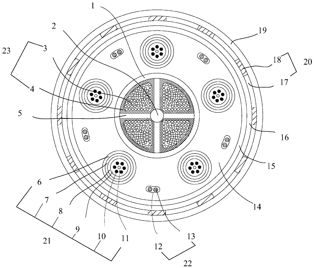
[0029] Such as figure 1 As shown, a composite cable in this embodiment includes: a first strengthening core 2, a plurality of baffles 5, a plurality of conductive cores 23, a first shielding layer 1, a plurality of optical fiber cores 21, a second The shielding layer 15, the cable outer sheath 19 and the first filling layer 14; the outer peripheral side of the first reinforcing core 2 is evenly and fixedly connected with a plurality of baffles 5, and each two adjacent baffles 5 are provided in the cavity formed There is a conductive wire core 23, the first shielding layer 1 is sleeved on the outside of all the baffles 5, the second shielding layer 15 is sleeved on the outer peripheral side of the first shielding lay...


PUM

PropertyMeasurementUnit
diameteraaaaaaaaaa

Abstract

The invention relates to a composite cable, comprising: a plurality of baffles are uniformly and fixedly connected to the outer peripheral side of a first reinforcing core, conductive wire cores are arranged in the cavities formed between every two adjacent baffles, and the first shielding Layers are sleeved on the outside of all baffles, the second shielding layer is sleeved on the outer peripheral side of the first shielding layer and forms an annular cavity with the first shielding layer, and multiple optical fiber cores are evenly arrayed around the axis of the annular cavity Distributed in the annular cavity, the gap between the first shielding layer, the second shielding layer and multiple optical fiber cores is filled with the first filling layer, and the outer sheath of the cable is sleeved on the outer peripheral side of the second shielding layer; through this The invention realizes the integration of conductive transmission and signal transmission functions, reduces the signal interference between various cables, and improves the tensile and bending strength of the composite cable. Positioning is simple.

Description

technical field [0001] The invention relates to the field of cables, in particular to a composite cable. Background technique [0002] At present, most cables are used for connecting wires for transmission and distribution of electric energy, and are widely used in the electrical field. Most cables are formed by wrapping and winding conductors with an outer insulating layer, and the conductors are provided with shielding layers or armor. A cable for optical signal transmission of communication signals. In the prior art, the optical cable and the cable are mostly set separately, and when the cable or the optical cable is broken due to external factors such as strong wind or snow accumulation, the location of the broken cable cannot be found in time and fixed. It was repaired in time, and at the same time, the inaccurate positioning of the multiple wire groups in the cable due to the circular cross section caused the winding of the multi-strand cable core to be difficult, and ...

Claims


Application Information

Patent Timeline
Patent Type & Authority Patents(China)
IPC IPC(8): H01B9/00H01B9/02H01B7/18H01B7/22H01B7/02H01B7/28H01B7/29H01B7/295H01B7/36H01B7/32H01B7/40H01B7/42G02B6/44
CPCH01B7/02H01B7/1815H01B7/1825H01B7/1875H01B7/223H01B7/226H01B7/2806H01B7/29H01B7/295H01B7/328H01B7/361H01B7/40H01B7/425H01B7/428H01B9/005H01B9/006H01B9/02H01B9/024G02B6/443G02B6/44384
Inventor 郝飞雄高志军刘雪娇
Owner 内蒙古万蒙电缆有限责任公司
Why Eureka
Try Eureka