
Compressor winding heating control method and device

A control method and technology of a control device, applied in the field of compressors, can solve problems such as mechanical wear and failure of compressors, and achieve the effect of improving low-temperature heating capacity

Active Publication Date: 2018-12-07
GD MIDEA AIR-CONDITIONING EQUIP CO LTD +1
View PDF7 Cites 14 Cited by
  • Summary
  • Abstract
  • Description
  • Claims
  • Application Information

AI Technical Summary

Problems solved by technology

However, there is an upper limit to the operating speed of the compressor, and if the speed is too high, it will cause mechanical wear and failure of the compressor

Method used


Image

  • Compressor winding heating control method and device
  • Compressor winding heating control method and device
  • Compressor winding heating control method and device

Examples


Embodiment Construction

[0044] Embodiments of the present invention are described in detail below, examples of which are shown in the drawings, wherein the same or similar reference numerals designate the same or similar elements or elements having the same or similar functions throughout. The embodiments described below by referring to the figures are exemplary only for explaining the present invention and should not be construed as limiting the present invention.

[0045] A method and device for controlling heating of a compressor winding according to an embodiment of the present invention will be described below with reference to the accompanying drawings.

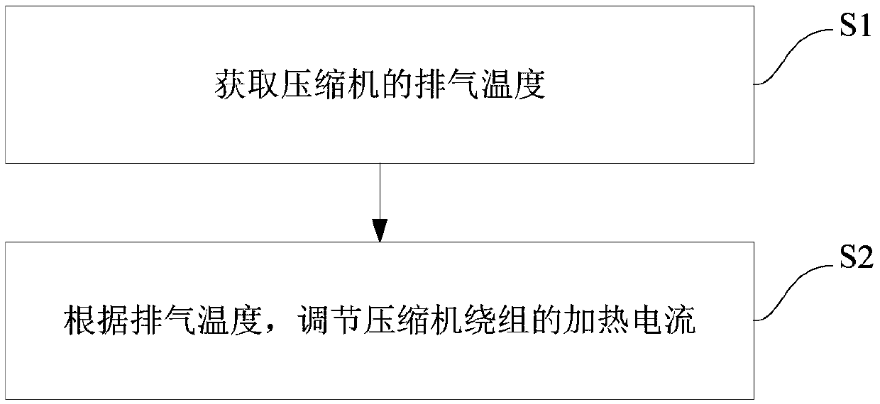
[0046] figure 1 It is a flowchart of a method for controlling heating of compressor windings according to an embodiment of the present invention. like figure 1 As shown, the method includes the following steps:

[0047] Step S1: Obtain the discharge temperature of the compressor.

[0048] Step S2: Adjust the heating current of the compress...


PUM


Abstract

The invention provides a compressor winding heating control method and device. The method comprises the following steps: the exhaust temperature of a compressor is obtained; and the heating current ofcompressor windings is adjusted according to the exhaust temperature. Through heating of the compressor windings, heat of refrigerants is absorbed to transfer to an indoor unit evaporator through thewindings, so that the low-temperature heating capacity is improved.

Description

technical field [0001] The invention relates to the technical field of compressors, in particular to a method and device for controlling heating of compressor windings. Background technique [0002] Low-temperature heating has always been a technical difficulty of the inverter air-conditioning system, including the technology of painting the enthalpy-increasing variable-frequency compressor and the technology of two-stage compression variable-frequency compressor to solve the problem of low-temperature heating. [0003] At present, in the case of not using a specially designed compressor, in order to increase the low-temperature heating capacity, it can only be achieved by increasing the compressor speed. However, there is an upper limit to the operating speed of the compressor, and if the speed is too high, it will cause the mechanical wear of the compressor and cause it to fail. Contents of the invention [0004] The present invention aims at solving one of the technica...

Claims


Application Information

Patent Timeline
Patent Type & Authority Applications(China)
IPC IPC(8): F24F11/89F24F11/88F24F11/64F24F11/86F04B49/00
CPCF04B49/00F24F2221/34F24F11/64F24F11/86F24F11/88F24F11/89
Inventor 黄招彬
Owner GD MIDEA AIR-CONDITIONING EQUIP CO LTD
Learn More