Embedded speed-locked friction pendulum damping mounting support
A speed-locking, shock-absorbing support technology, applied to bridge parts, bridges, buildings, etc., can solve the problems of inability to perform full-displacement shock absorption, weak shock absorption, etc., to meet normal displacement needs, avoid impact, and avoid no damping The effect of shock or weak shock absorption
- Summary
- Abstract
- Description
- Claims
- Application Information
AI Technical Summary
Problems solved by technology
Method used
Image
Examples
Embodiment 1
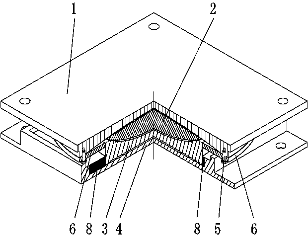
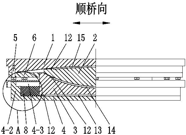
[0034] Such as Figures 1 to 7As shown, the embedded speed-locking friction pendulum shock-absorbing support includes an upper support plate 1, a spherical plate 2, a middle steel plate 3 and a lower support plate 4 from top to bottom. The upper support plate 1 is used to connect with the bridge body connection, the lower bearing plate 4 is used to connect with the pier, the upper end surface and the lower end surface of the spherical panel 2 are spherical, the upper end surface protrudes upwards, and the lower end surface protrudes downwards, the horizontal projection of the spherical panel 2 is circular, and the upper end surface The lower end surface of the bearing plate 1 matches the upper end surface of the spherical plate 2 and the radius of curvature of the two is the same, the lower end surface of the upper bearing plate 1 is sunken upwards, the upper end surface of the middle steel plate 3 matches the lower end surface of the spherical plate 2 and both The radius of c...
Embodiment 2
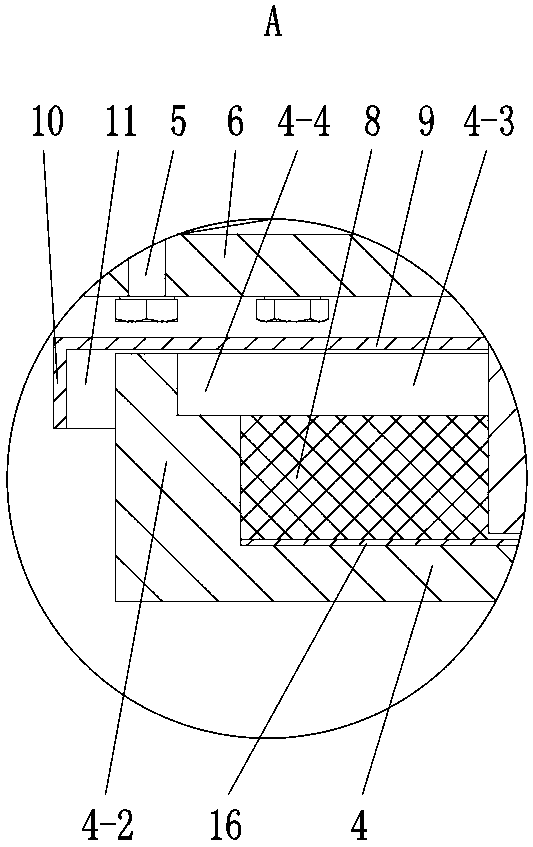
[0040] Such as Figures 2 to 7 As shown, on the basis of Embodiment 1, during initial installation, the top surface of the speed lock layer 8 is lower than the top surface of the groove wall 4-2, so that the deformation compensation area 4-3 is formed above the speed lock layer 8, and the deformation compensation The overflow area 4-3 surrounds the middle steel plate 3, and the deformation supplement overflow area 4-3 belongs to the installation groove 4-1; further, additional grooves 4-4 are provided on the groove wall 4-2, and the additional grooves 4-4 are located on the groove wall 4 The inner side of the top of -2 is connected with the installation groove 4-1, and the additional groove 4-4 expands the size of the deformation filling area 4-3 in the horizontal direction, and the additional groove 4-4 is along the inner edge of the top of the groove wall 4-2 Setting; when there is a normal displacement between the middle steel plate 3 and the lower support plate 4, the midd...
Embodiment 3
[0042] On the basis of Embodiment 2, there are through holes (not shown in the figure) along the bridge and through holes (not shown in the figure) in the middle steel plate 3, both of which are horizontal. The bridge to the through hole is used to communicate with the installation groove 4-1 area on the front and rear sides of the middle steel plate 3, and the transverse bridge to the through hole is used to connect to the installation groove 4-1 area on the left and right sides of the middle steel plate 3; when the middle steel plate 3 and the lower support plate When there is a normal displacement between 4, the middle steel plate 3 slowly squeezes the lock layer 8, and the shear-thickening material therein deforms slowly, and the through-holes along the bridge and the through-holes towards the cross-bridge can further effectively provide the shear-thickening material The deformation provides a place to go, and the shear thickening material can go from the extruded installat...
PUM
 Abstract
Description
Claims
Application Information
 - R&D Engineer
- R&D Manager
- IP Professional
- Industry Leading Data Capabilities
- Powerful AI technology
- Patent DNA Extraction
Browse by: Latest US Patents, China's latest patents, Technical Efficacy Thesaurus, Application Domain, Technology Topic, Popular Technical Reports.
© 2024 PatSnap. All rights reserved.Legal|Privacy policy|Modern Slavery Act Transparency Statement|Sitemap|About US| Contact US: help@patsnap.com


