
Cleaning type sheet metal part punching device

A technology for punching devices and sheet metal parts, which is applied in the direction of feeding devices, storage devices, positioning devices, etc., and can solve problems such as poor stability of sheet metal parts, low reliability in use, and inability to clamp sheet metal parts

Inactive Publication Date: 2018-12-07
河北能源职业技术学院
View PDF0 Cites 10 Cited by
  • Summary
  • Abstract
  • Description
  • Claims
  • Application Information

AI Technical Summary

Problems solved by technology

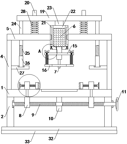
[0002] As we all know, the clean sheet metal punching device is an auxiliary device for punching the designated position of the clean sheet metal so that the clean sheet metal can be better assembled with other parts. It has been widely used in the field of sheet metal parts processing; the existing clean sheet metal parts punching device includes workbench, left support plate, right support plate, left clamp plate, right clamp plate, left support plate, right support plate plate, top plate and hydraulic cylinder, the tops of the left support plate and the right support plate are respectively connected with the left and right sides of the bottom end of the workbench, and the bottom ends of the left clamp plate and the right clamp plate are respectively connected with the left side and right side of the top end of the workbench. connection, the bottom ends of the left support plate and the right support plate are respectively connected with the left and right sides of the top of the workbench, and the tops of the left support plate and the right support plate are respectively connected with the left and right sides of the bottom end of the top plate, and the hydraulic cylinder The top is connected to the bottom middle of the top plate, and the bottom output end of the telescopic cylinder inside the hydraulic cylinder is provided with a punching head, and the top middle of the workbench is provided with a punching groove; when the existing clean sheet metal punching device is used, First place the sheet metal parts to be punched on the workbench, then clamp them tightly with the left and right clamps, then find the punching position, connect the hydraulic cylinder with the external hydraulic station through the hydraulic oil pipe, and turn on the hydraulic pressure. Cylinder, move the punching head down under the drive of the telescopic rod inside the hydraulic cylinder, and punch the sheet metal parts; in the use of the existing clean sheet metal parts punching device, it is found that the sheet metal parts The stability on the board is poor, and the sheet metal parts cannot be clamped well by the left clamping plate and the right clamping plate, resulting in low reliability in use; and the punching head cannot be fixed in time after punching the sheet metal parts. Detachment from the sheet metal parts makes the sheet metal parts easy to move up with the punching head when it is lifted up, which affects its punching effect and leads to poor practicability

Method used


Image

  • Cleaning type sheet metal part punching device
  • Cleaning type sheet metal part punching device
  • Cleaning type sheet metal part punching device

Examples


Embodiment Construction

[0017] The specific implementation manners of the present invention will be further described in detail below in conjunction with the accompanying drawings and embodiments. The following examples are used to illustrate the present invention, but are not intended to limit the scope of the present invention.

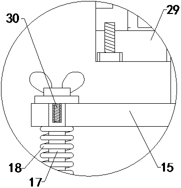
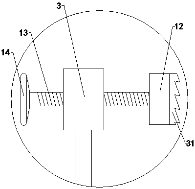
[0018] Such as Figure 1 to Figure 3 As shown, a clean sheet metal punching device of the present invention includes a workbench 1, a left support plate 2, a right support plate, a left support plate 3, a right support plate, a left support plate 4, a right support plate, and a top plate 5 and hydraulic cylinder 6, the tops of the left support plate 2 and the right support plate are respectively connected with the left side and the right side of the bottom end of the workbench 1, and the bottom ends of the left support plate 4 and the right support plate are connected with the left side of the top end of the workbench 1 respectively. It is connected with the right side, a...


PUM


Abstract

The invention relates to the technical field of sheet metal part machining accessory devices, in particular to a cleaning type sheet metal part punching device. By means of the device, stability, achieved on a workbench, of a sheet metal part can be improved; the sheet metal part can be well clamped through a left clamping plate and a right clamping plate; use reliability is improved; in addition,after punching of the sheet metal part is completed, a punching head can be separated from the sheet metal part conveniently in time, and the problem that the sheet metal part is likely to move upwards in the process that the punching head is lifted, so that the punching effect is affected is prevented; and practicability is improved. The cleaning type sheet metal part punching device comprises the workbench, a left support plate, a right support plate, the left clamping plate, the right clamping plate, a left supporting plate, a right supporting plate, a top plate, a hydraulic cylinder, a left moving block, a right moving block, a left lead screw, a right lead screw, a fixing block, a first hand wheel, a left clamp plate, a right clamp plate, a left threaded rod, a right threaded rod, aleft second hand wheel, a right second hand wheel, an upper fixing ring, a lower support ring, four lower limiting sliding pillars and four support springs. The top ends of the four lower limiting sliding pillars are each provided with a baffle.

Description

technical field [0001] The invention relates to the technical field of accessory devices for processing sheet metal parts, in particular to a clean punching device for sheet metal parts. Background technique [0002] As we all know, the clean sheet metal punching device is an auxiliary device for punching the designated position of the clean sheet metal so that the clean sheet metal can be better assembled with other parts. It has been widely used in the field of sheet metal parts processing; the existing clean sheet metal parts punching device includes workbench, left support plate, right support plate, left clamp plate, right clamp plate, left support plate, right support plate plate, top plate and hydraulic cylinder, the tops of the left support plate and the right support plate are respectively connected with the left and right sides of the bottom end of the workbench, and the bottom ends of the left clamp plate and the right clamp plate are respectively connected with t...

Claims


Application Information

Patent Timeline
Patent Type & Authority Applications(China)
IPC IPC(8): B21D28/34B21D28/26B21D43/00
CPCB21D28/34B21D28/26B21D43/003
Inventor 于敬华梁冠英王蕊
Owner 河北能源职业技术学院
Learn More