
A dust bucket support base

A technology for supporting bases and dust hoppers, applied in separation methods, dispersed particle separation, chemical instruments and methods, etc., can solve problems such as being easily affected by wind and rain, dust removal operations, and unfavorable waste gas treatment

Active Publication Date: 2020-07-07
MAANSHAN SHUNDA ENVIRONMENTAL PROTECTION EQUIP
View PDF5 Cites 0 Cited by
  • Summary
  • Abstract
  • Description
  • Claims
  • Application Information

AI Technical Summary

Problems solved by technology

[0005] The purpose of the present invention is to provide a support base for the dust collection hopper, to solve the above mentioned background technology for the placement of the dust collection hopper in the industry, most of them are directly supported by iron frame welding, although the structure is simple, it is not conducive to the dust collection hopper The dust discharge operation of the bucket cavity is easily affected by wind and rain during the dust discharge process of the dust collection bucket, which is not conducive to the timely dust discharge operation of the bucket cavity of the dust collection bucket, thus affecting the normal operation of the dust collector. When the dust collector cannot be used , it is necessary to stop the boiler operation to avoid exhaust gas pollution to the environment, thereby slowing down the work efficiency of the industry. If the boiler operation is not stopped, because the dust collector cannot be used, the exhaust gas generated by the boiler operation will directly cause exhaust gas pollution to the surrounding environment, which is not conducive to environmental protection. Problems that are not conducive to timely treatment of exhaust gas

Method used


Image

  • A dust bucket support base
  • A dust bucket support base
  • A dust bucket support base

Examples


Embodiment Construction

[0022] The following will clearly and completely describe the technical solutions in the embodiments of the present invention with reference to the accompanying drawings in the embodiments of the present invention. Obviously, the described embodiments are only some, not all, embodiments of the present invention. Based on the embodiments of the present invention, all other embodiments obtained by persons of ordinary skill in the art without creative efforts fall within the protection scope of the present invention.

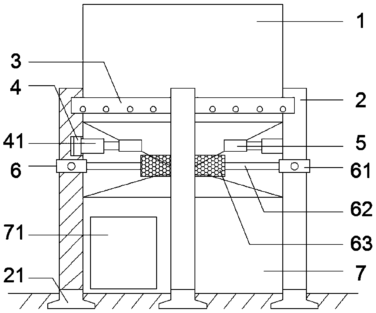
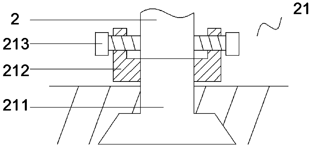
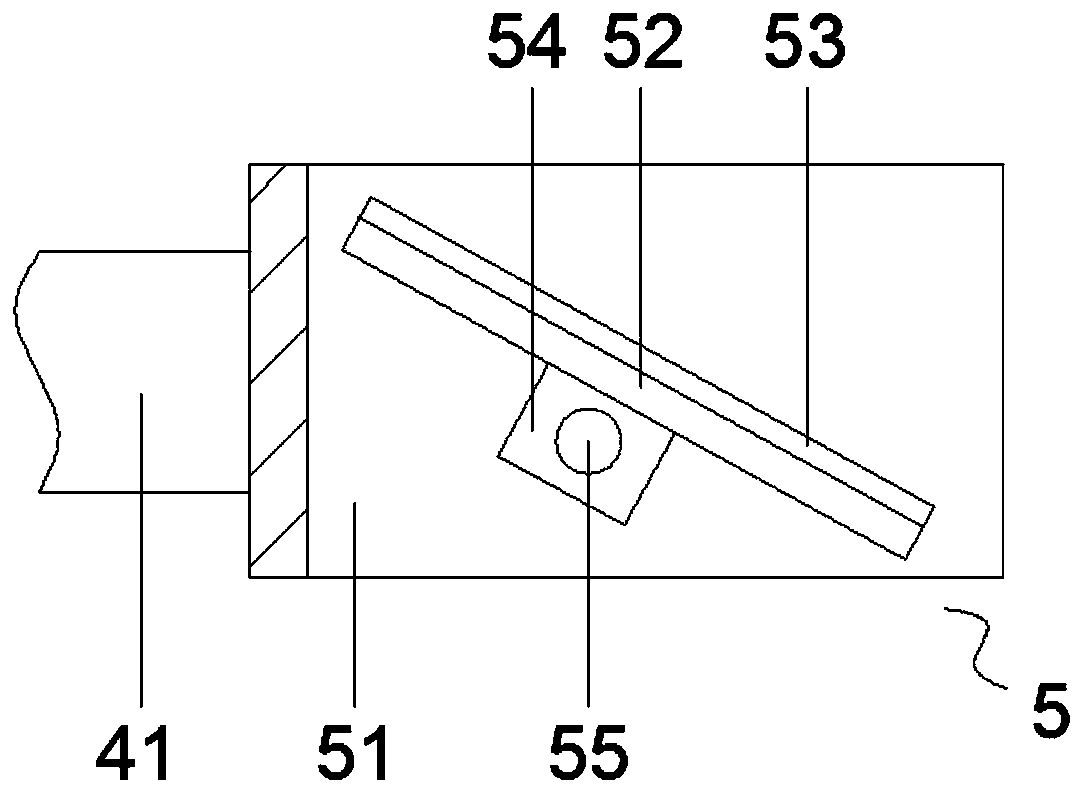
[0023] see Figure 1-4 , the present invention provides a technical solution: a dust hopper support base, including a dust hopper 1, the outer wall of the dust hopper 1 is evenly installed with a support column 2 and a drainage groove 3, and the support column 2 and the drainage groove 3 are arranged alternately , the bottom of the support column 2 is connected with the base column 21, the bottom of the base column 21 is buried in the ground, the upper part of the ...


PUM


Abstract

The invention discloses a dust collecting hopper supporting base relating to the technical field of dedusters. The dust collecting hopper supporting base includes a dust collecting hopper. The outer side wall of the dust collecting hopper is uniformly provided with supporting columns and drainage grooves, and the supporting columns and the drainage grooves are alternately distributed. A base column is connected to the bottom of the supporting column. The bottom of the base column is buried underground. The upper part of the supporting column is provided with a groove cavity. A hydraulic motoris mounted in the groove cavity. The dust collecting hopper supporting base enables people to carry out dust discharge operation on the cavity of the dusting collecting hopper in windy and rainy weather, helps people to timely carry out dust discharging on the cavity of the dust collecting hopper so as to avoid affecting the normal operation of a deduster, avoids stopping boiler operation due to the failure of discharge dust from the dust collecting hopper in time, avoids slowing down the work efficiency of the industry, facilitates the deduster to carry out dedusting treatment on exhaust gasin time, facilitates environment protection, and reduces pollution of the boiler exhaust gas to the surrounding environment.

Description

technical field [0001] The invention relates to the technical field of dust collectors, in particular to a support base for a dust collecting bucket. Background technique [0002] Dust collector is a device that separates dust from flue gas, called dust collector or dust removal equipment. The performance of the dust collector is expressed by the amount of gas that can be handled, the resistance loss when the gas passes through the dust collector, and the dust removal efficiency. At the same time, the price, operation and maintenance costs, service life and difficulty of operation and management of the dust collector are also important factors to consider its performance. Dust collectors are commonly used facilities in boilers and industrial production. [0003] Negative pressure blowback filter bag dust collector is used to control the exhaust gas pollution of industrial boilers. Small footprint, large filtration area, stable working performance, high purification effici...

Claims


Application Information

Patent Timeline
Patent Type & Authority Patents(China)
IPC IPC(8): B01D46/48B01D46/00
CPCB01D46/001B01D46/48
Inventor 王春保
Owner MAANSHAN SHUNDA ENVIRONMENTAL PROTECTION EQUIP
Learn More