Chopping and filament-drawing flail knife

A knife-throwing and wire-drawing technology, applied in cutting equipment, agricultural machinery and implements, applications, etc., can solve problems such as troublesome operation, time-consuming work, and a large amount of manpower, and achieve a reasonable and novel structure design effect

Pending Publication Date: 2018-12-07
包青春
View PDF10 Cites 0 Cited by
  • Summary
  • Abstract
  • Description
  • Claims
  • Application Information

AI Technical Summary

Problems solved by technology

[0003] The existing kneading machine needs to manually feed the straw crops into the feeding port, and through the cooperation of the movable knife and the fixed knife, the straw is chopped and kneaded. near the machine, which not only takes time, but also requires a lot of manpower, so the operation is very troublesome

Method used


Image

  • Chopping and filament-drawing flail knife
  • Chopping and filament-drawing flail knife
  • Chopping and filament-drawing flail knife

Examples


specific Embodiment approach 1

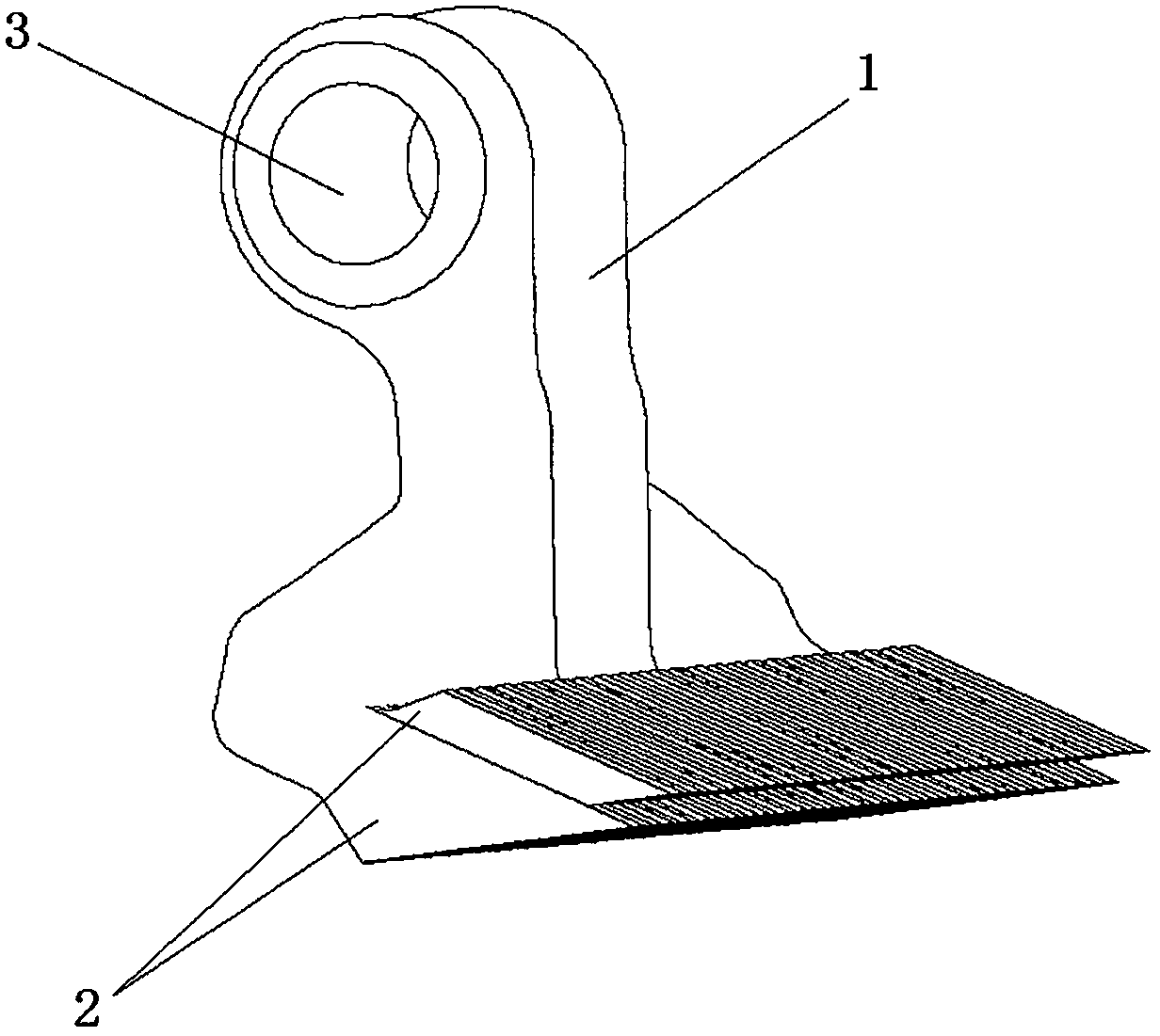
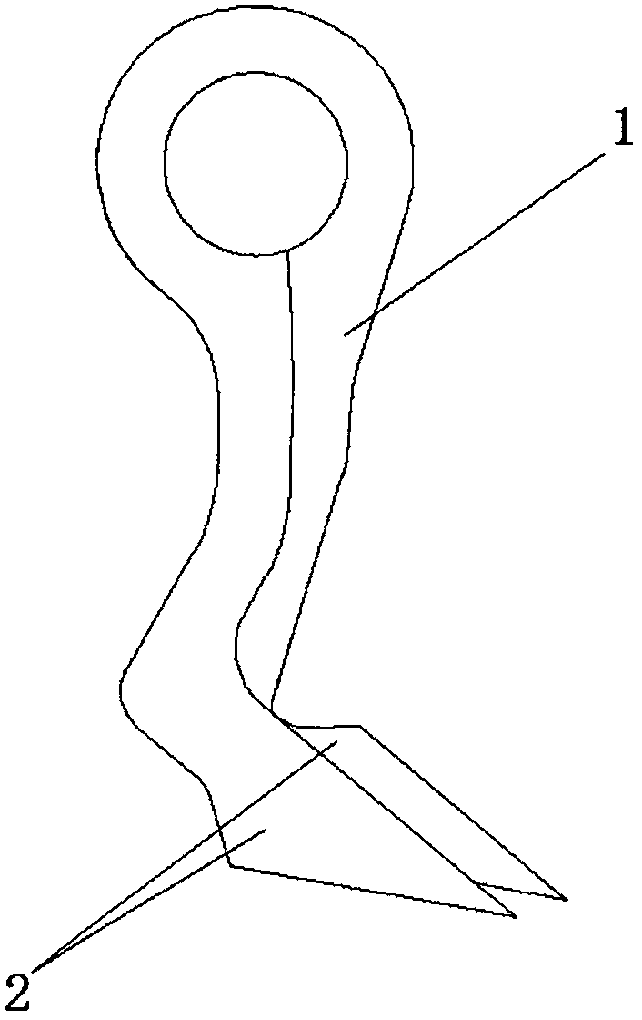
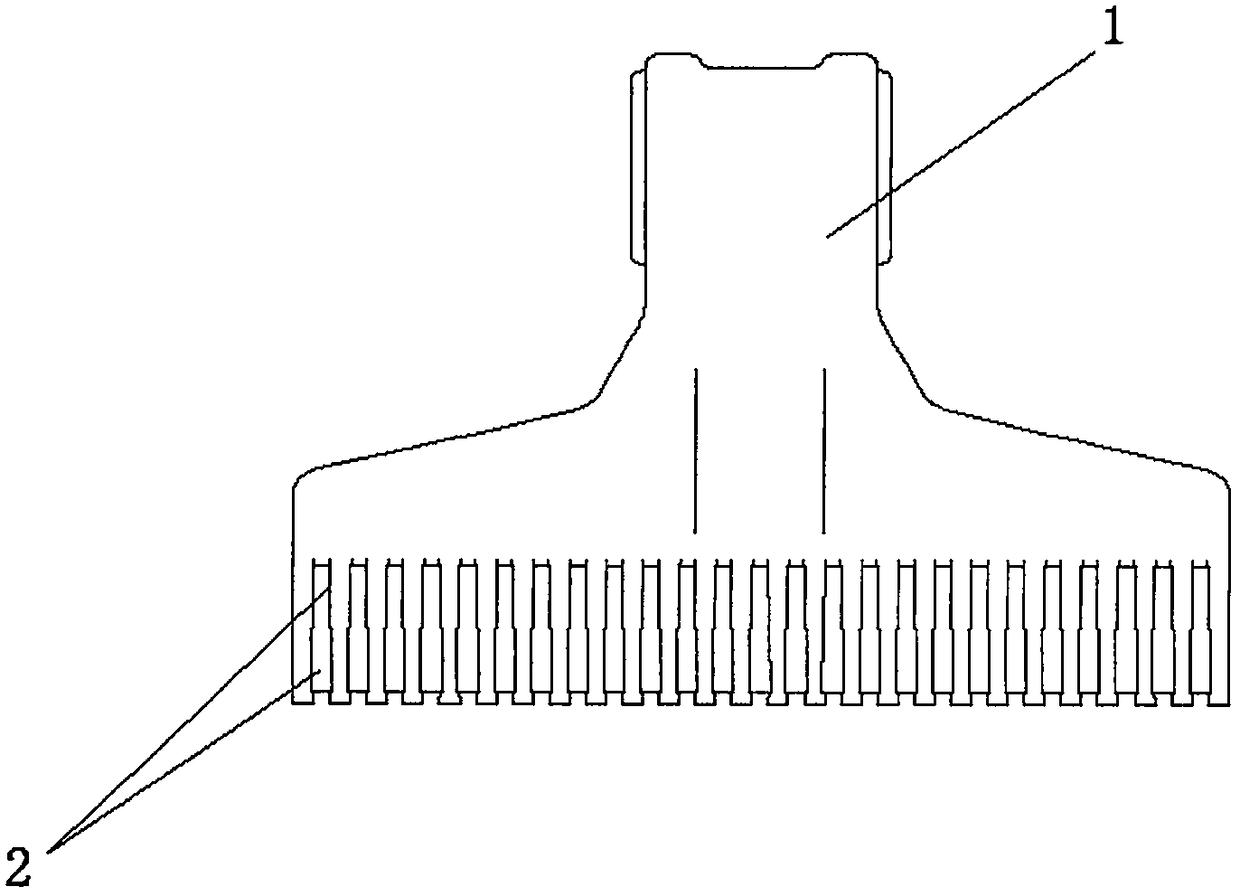
[0015] Specific implementation mode one: please refer to Figure 1-3 , the present invention provides a technical solution: a chopping and drawing flinging knife, comprising a flinging knife body 1, a flinging blade 2 and a mounting hole 3, the upper part of the flinging knife body 1 is provided with a mounting hole 3, and the lower part of the flinging knife body 1 is arranged There are two layers of throwing blades 2, and the two layers of throwing blades 2 are arranged in a staggered arrangement up and down.

[0016] Preferably, the flail knife body 1 and flail blade 2 are formed by integral casting or forging of metal materials.

specific Embodiment approach 2

[0017] Specific implementation mode two: refer to Figure 4-6 The difference between this specific embodiment and specific embodiment 1 is that there are three or more layers of flail blades 2 under the flail body 1, and the three or multi-layer flail blades 2 are arranged in a staggered manner. , the other composition and connection methods are the same as those in Embodiment 1.


PUM


Abstract

The invention discloses a chopping and filament-drawing flail knife, and relates to the technical field of filament-drawing machines. The chopping and filament-drawing flail knife comprises a flail knife body, flail knife blades and a mounting hole, wherein the upper part of the flail knife body is provided with the mounting hole; and the lower part of the flail knife body is provided with two layers of flail knife blades which are in staggered arrangement from top to bottom. The chopping and filament-drawing flail knife provided by the invention has reasonable and novel design; the flail knife blades are designed into two layers, three layers or a plurality of layers, are made of a metal material by casting or forging, and is sturdy and durable; by combination of a conventional straw ensiling machine and through high-speed rotation of the chopping and filament-drawing flail knife, straw can be instantly chopped and cut off for drawing filaments; and compared with a conventional strawfilament-kneading machine, the chopping and filament-drawing flail knife saves a majority of works like straw harvesting, straw transportation and manual feeding, so time and labor are saved.

Description

technical field [0001] The invention relates to the technical field of silk kneading machine equipment, in particular to a shredding and drawing knife. Background technique [0002] The straw kneading machine is mainly used for the shredding and processing of plant straws such as cotton stalks, branches, bark, and straw with a diameter of less than 2 cm. It can also be used for shredding and processing of various crop straws and pastures. , wood-based panels, ethanol extraction, etc. The straw kneading machine is mainly used for the shredding and processing of biomass such as cotton stalks, branches, corn stalks, straw, etc. The equipment can be matched with motors, diesel engines or 30-56 horsepower tractors, and the main machine is fed by Mechanism, guillotine cutting mechanism, throwing mechanism, transmission mechanism, walking mechanism, protective device and frame, etc., which have the characteristics of reasonable structure, convenient movement, automatic feeding, saf...

Claims


Application Information

Patent Timeline
Patent Type & Authority Applications(China)
IPC IPC(8): A01F29/09
CPCA01F29/09
Inventor 包青春
Owner 包青春
Why Eureka
Try Eureka