
An Optimal Method for Antenna Transceiver Device Including Polarization Parameters

A transceiver device, polarization parameter technology, applied in antennas, antenna arrays, multi-objective optimization and other directions, can solve the problems of single transceiver antenna, phase difference between two polarization components, lack of calculation and optimization methods, etc.

Active Publication Date: 2022-04-19
CHINA ACADEMY OF INFORMATION & COMM
View PDF5 Cites 0 Cited by
  • Summary
  • Abstract
  • Description
  • Claims
  • Application Information

AI Technical Summary

Problems solved by technology

Traditionally, the Fries formula is used to calculate the transmit and receive loss of the free space antenna. The Fries formula itself does not include the polarization component. Some subsequent formulas consider the transmit and receive loss when the polarization of the transmit and receive antenna does not match, but these formulas are all assumptions Both transmit and receive antennas are single linearly polarized
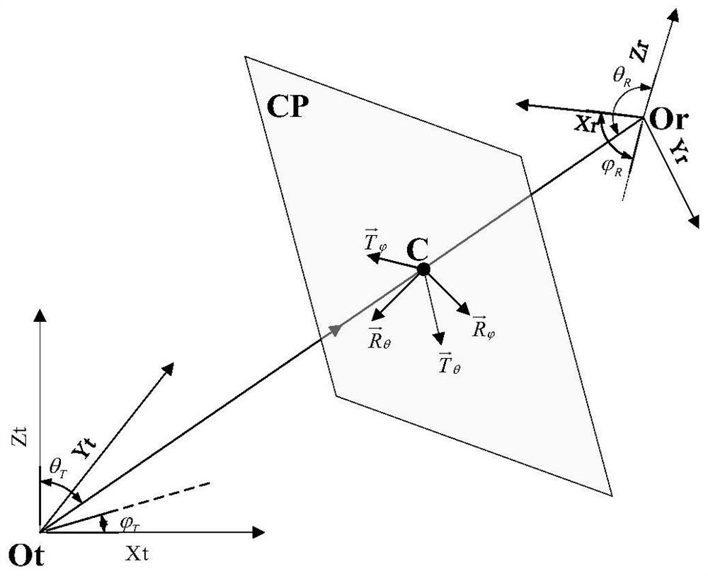
However, the antennas used in practical engineering generally contain two polarization components, and there is a phase difference between the two polarization components. In this case, there is a lack of calculation and optimization methods

Method used


Image

  • An Optimal Method for Antenna Transceiver Device Including Polarization Parameters
  • An Optimal Method for Antenna Transceiver Device Including Polarization Parameters
  • An Optimal Method for Antenna Transceiver Device Including Polarization Parameters

Examples


Embodiment 1

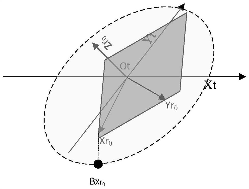
[0159] Calculate the transmission loss of 28GHz transceiver and two spatial relationships: 1. The two double-ridged horn antennas have a certain height difference. 2. The height of the two double-ridged horn antennas is the same.

[0160] From Figure 6 and Figure 7 It can be seen that the calculated value of the transmission loss considering dual polarization is larger than that of the traditional one without considering polarization, which is a common phenomenon. That is to say, if the case of dual polarization is not considered, the estimation of the transmission loss is relatively small.

Embodiment 2

[0162] Combined with the differential genetic algorithm, the maximum value of (28) and the antenna space phase position parameter corresponding to the maximum value can be obtained. The iterative result of a typical differential genetic algorithm is as follows: Figure 8 As shown, the calculation results without considering the polarization are used as reference values ​​for normalization.


PUM


Abstract

The present invention relates to the technical field of antenna transceiving, and provides an optimization method of an antenna transceiving device including polarization parameters. The method takes the phase of two polarization components included in the transceiving antenna as the dependent variable, and the phase includes spatial polarization Angle and time phase; Finally, the relational expression between the transmitting and receiving transmission loss of the antenna and the dependent variable is obtained, and the phase of the transmitting and receiving antenna is optimized according to the relational expression to reduce the transmission loss of the transmitting and receiving antenna. The invention solves the defect that the antenna transmission loss obtained by using the Fries formula to calculate the antenna transmission is too small; according to the method, multiple groups of transmitting and receiving antenna parameters that can realize the maximum receiving power can be obtained, and the antenna is optimized according to the parameters .

Description

technical field [0001] The invention relates to the technical field of antenna transceiving, in particular to an optimization method of an antenna transceiving device including polarization parameters. Background technique [0002] The calculation of antenna transmission and reception loss is the core issue of radio science, and has important applications in the fields of radio wave propagation prediction, wireless communication system design, radar detection, radio measurement involving electromagnetic fields and antennas, electromagnetic interference and compatibility, etc. Traditionally, the Fries formula is used to calculate the transmit and receive loss of the free space antenna. The Fries formula itself does not include the polarization component. Some subsequent formulas consider the transmit and receive loss when the polarization of the transmit and receive antenna does not match, but these formulas are all assumptions The transmit and receive antennas are all single...

Claims


Application Information

Patent Timeline
Patent Type & Authority Patents(China)
IPC IPC(8): G06F30/17G06F30/27H01Q15/24H01Q21/00G06F111/06
CPCH01Q15/24H01Q21/00G06F30/17G06F2111/10
Inventor 周峰张培艳张向阳张颖艳周开波孟艾立宋振飞林浩宇
Owner CHINA ACADEMY OF INFORMATION & COMM
Learn More