Method and device in ue and base station used for wireless communication

a wireless communication and wireless communication technology, applied in wireless communication, transmission path sub-channel allocation, transmission path division, etc., can solve the problems of affecting system capacity, wasting resources, and hardly meeting the growing demand for traffic, so as to improve system capacity, increase uplink transmission resources, and accurate channel information

Active Publication Date: 2020-11-12
SHANGHAI LANGBO COMM TECH CO LTD
View PDF7 Cites 2 Cited by
  • Summary
  • Abstract
  • Description
  • Claims
  • Application Information

AI Technical Summary

Benefits of technology

The patent text describes a method that uses two uplink reference signals to assist a base station in acquiring complete downlink channel information. This is useful even if one of the reference signals fails due to LBT failure. By using the reserved multicarrier symbols for the reference signals, the base station can obtain more accurate channel information which improves the system capacity. The method also takes into account beam-based LBTs which can reflect interference and improve sharing of the Unlicensed Spectrum.

Problems solved by technology

However, as traffic flow began to skyrocket, particularly in some urban areas, the Licensed Spectrum may hardly meet growing demands for traffic, therefore, in Release 13 and Release 14 communications on Unlicensed Spectrum is introduced into a cellular system and used for downlink and uplink data transmissions.
In one embodiment, a problem that needs solving in the present disclosure is that: in NR system, sufficient multicarrier symbols may need to be reserved between the two uplink radio signals for transmission antenna switching, since LBT, no matter it is omnidirectional or beam-based, may lead to a situation where one of the pre-configured uplink radio signals fails to be transmitted, so that multicarrier symbols reserved for the uplink radio signal not transmitted and for antenna switching cannot be adequately utilized, thereby causing wastes of resources and affecting the system capacity.

Method used


Image

  • Method and device in ue and base station used for wireless communication
  • Method and device in ue and base station used for wireless communication
  • Method and device in ue and base station used for wireless communication

Examples


embodiment 1

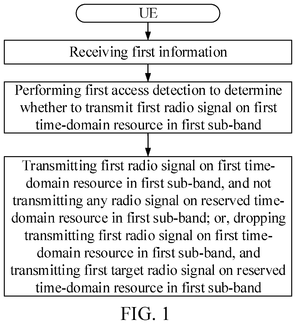
[0104]Embodiment 1 illustrates a flowchart of first information, a first access detection and a first radio signal, as shown in FIG. 1.

[0105]In Embodiment 1, the UE of the present disclosure receives first information, the first information being used to indicate a first time-domain resource and a second time-domain resource in a first sub-band, wherein the first time-domain resource is reserved for a first radio signal, and the second time-domain resource is reserved for a second radio signal; performs a first access detection to determine whether to transmit the first radio signal on the first time-domain resource in the first sub-band; and transmits the first radio signal on the first time-domain resource in the first sub-band, and does not transmit any radio signal on a reserved time-domain resource in the first sub-band; or, drops transmitting the first radio signal on the first time-domain resource in the first sub-band, and transmits a first target radio signal on the reserve...

embodiment 2

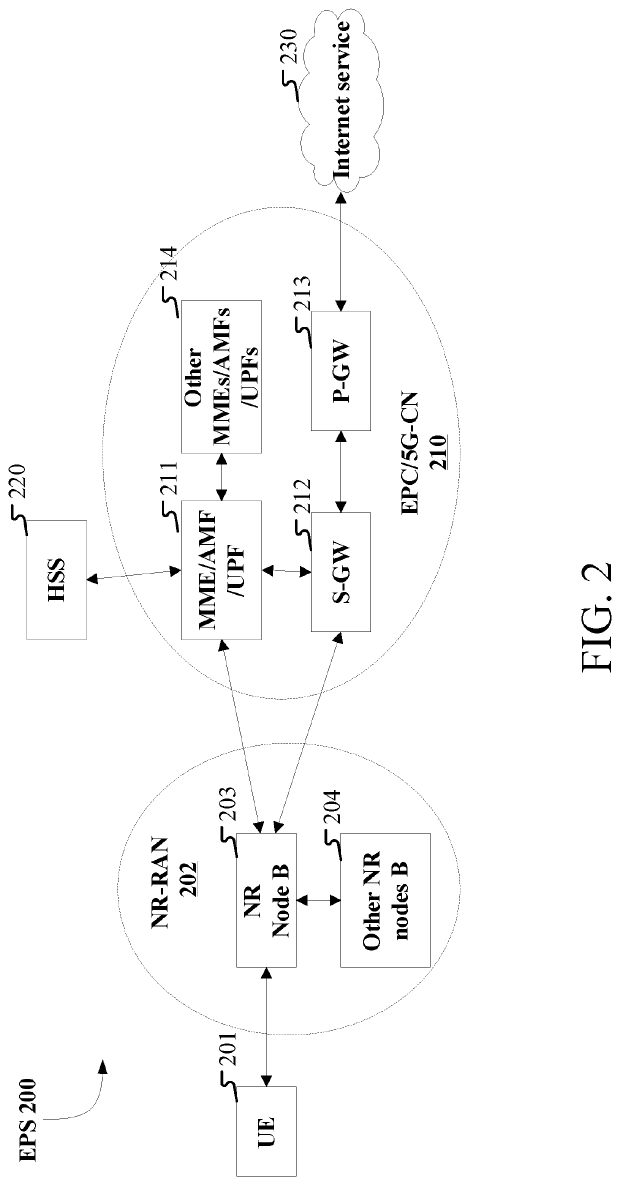
[0347]Embodiment 2 illustrates a schematic diagram of a network architecture, as shown in FIG. 2.

[0348]Embodiment 2 illustrates a schematic diagram of a network architecture according to the present disclosure, as shown in FIG. 2. FIG. 2 is a diagram illustrating a network architecture 200 of NR 5G, Long-Term Evolution (LTE), and Long-Term Evolution Advanced (LTE-A) systems. The NR 5G or LTE network architecture 200 may be called an Evolved Packet System (EPS) 200 or other appropriate terms. The EPS 200 may comprise one or more UEs 201, an NG-RAN 202, an Evolved Packet Core / 5G-Core Network (EPC / 5G-CN) 210, a Home Subscriber Server (HSS) 220 and an Internet Service 230. The EPS 200 may be interconnected with other access networks. For simple description, the entities / interfaces are not shown. As shown in FIG. 2, the EPS 200 provides packet switching services. Those skilled in the art will readily understand that various concepts presented throughout the present disclosure can be exte...

embodiment 3

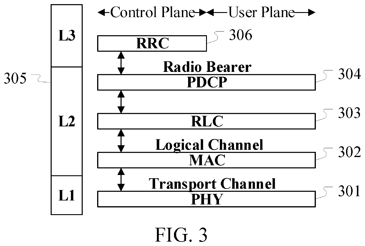
[0355]Embodiment 3 illustrates a schematic diagram of a radio protocol architecture of a user plane and a control plane, as shown in FIG. 3.

[0356]FIG. 3 is a schematic diagram illustrating a radio protocol architecture of a user plane and a control plane. In FIG. 3, the radio protocol architecture for a UE and a base station (gNB or eNB) is represented by three layers, which are a layer 1, a layer 2 and a layer 3, respectively. The layer 1 (L1) is the lowest layer and performs signal processing functions of various PHY layers. The L1 is called PHY 301 in the present disclosure. The layer 2 (L2) 305 is above the PHY 301, and is in charge of the link between the UE and the gNB via the PHY 301. In the user plane, L2305 comprises a Medium Access Control (MAC) sublayer 302, a Radio Link Control (RLC) sublayer 303 and a Packet Data Convergence Protocol (PDCP) sublayer 304. All the three sublayers terminate at the gNBs of the network side. Although not described in FIG. 3, the UE may compr...


PUM


Abstract

The present disclosure provides a method and device in a User Equipment (UE) and a base station used for wireless communications. The UE receives first information, the first information being used to indicate a first time-domain resource and a second time-domain resource in a first sub-band, wherein the first time-domain resource is reserved for a first radio signal; performs a first access detection to determine whether to transmit the first radio signal on the first time-domain resource in the first sub-band; and transmits the first radio signal on the first time-domain resource in the first sub-band, and does not transmit any radio signal on a reserved time-domain resource in the first sub-band; or, the UE drops transmitting the first radio signal on the first time-domain resource in the first sub-band. The reserved time-domain resource is located between the first time-domain resource and the second time-domain resource in time domain.

Description

CROSS REFERENCE TO RELATED APPLICATIONS[0001]This application is a continuation of International Application No. PCT / CN2019 / 074130, filed Jan. 31, 2019, claims the priority benefit of Chinese Patent Application No. 201810115784.0, filed on Feb. 6, 2018, the full disclosure of which is incorporated herein by reference.BACKGROUNDTechnical Field[0002]The present disclosure relates to transmission methods and devices in wireless communication systems, and in particular to a communication scheme and device that support data transmission on Unlicensed Spectrum.Related Art[0003]In a traditional 3rd Generation Partner Project (3GPP) Long-term Evolution (LTE) system, data transmission only occurs on Licensed Spectrum. However, as traffic flow began to skyrocket, particularly in some urban areas, the Licensed Spectrum may hardly meet growing demands for traffic, therefore, in Release 13 and Release 14 communications on Unlicensed Spectrum is introduced into a cellular system and used for down...

Claims


Application Information

Patent Timeline
Patent Type & Authority Applications(United States)
IPC IPC(8): H04W28/26H04W72/04
CPCH04W72/042H04W72/0446H04W72/0453H04W28/26H04L5/0048H04L5/0053H04L5/0057H04B7/0413H04B7/0626H04W74/0808H04B7/0695H04B7/0617H04B7/0691H04L5/0007H04L5/0078H04L5/0094H04W72/23
Inventor ZHANG, XIAOBO
Owner SHANGHAI LANGBO COMM TECH CO LTD
Why Eureka
Try Eureka