
High- and low-temperature switching test module

A test module, high and low temperature technology, applied in the field of test modules that can quickly switch between high and low temperatures, can solve the problems of expensive refrigeration chips, low production efficiency, and high temperature conversion

Active Publication Date: 2018-12-04
KING YUAN ELECTRONICS
View PDF9 Cites 8 Cited by
  • Summary
  • Abstract
  • Description
  • Claims
  • Application Information

AI Technical Summary

Problems solved by technology

[0003] At present, some of the modules for high and low temperature testing of chips use cooling chips and hot air generators to perform low temperature and high temperature tests on the chips to be tested in the cavity. Due to the large size of the cavity, the temperature in the cavity is not easy to change from low temperature to high temperature. It takes a lot of time to complete the high temperature and low temperature tests of the chip, and the production efficiency is very low
In addition, the temperature change of the cooling chip also takes a long time to stabilize, resulting in a longer test time, the price of the cooling chip is also more expensive, and the cost is also high, which is not very ideal, and there is still room for improvement

Method used


Image

  • High- and low-temperature switching test module
  • High- and low-temperature switching test module
  • High- and low-temperature switching test module

Examples


Embodiment Construction

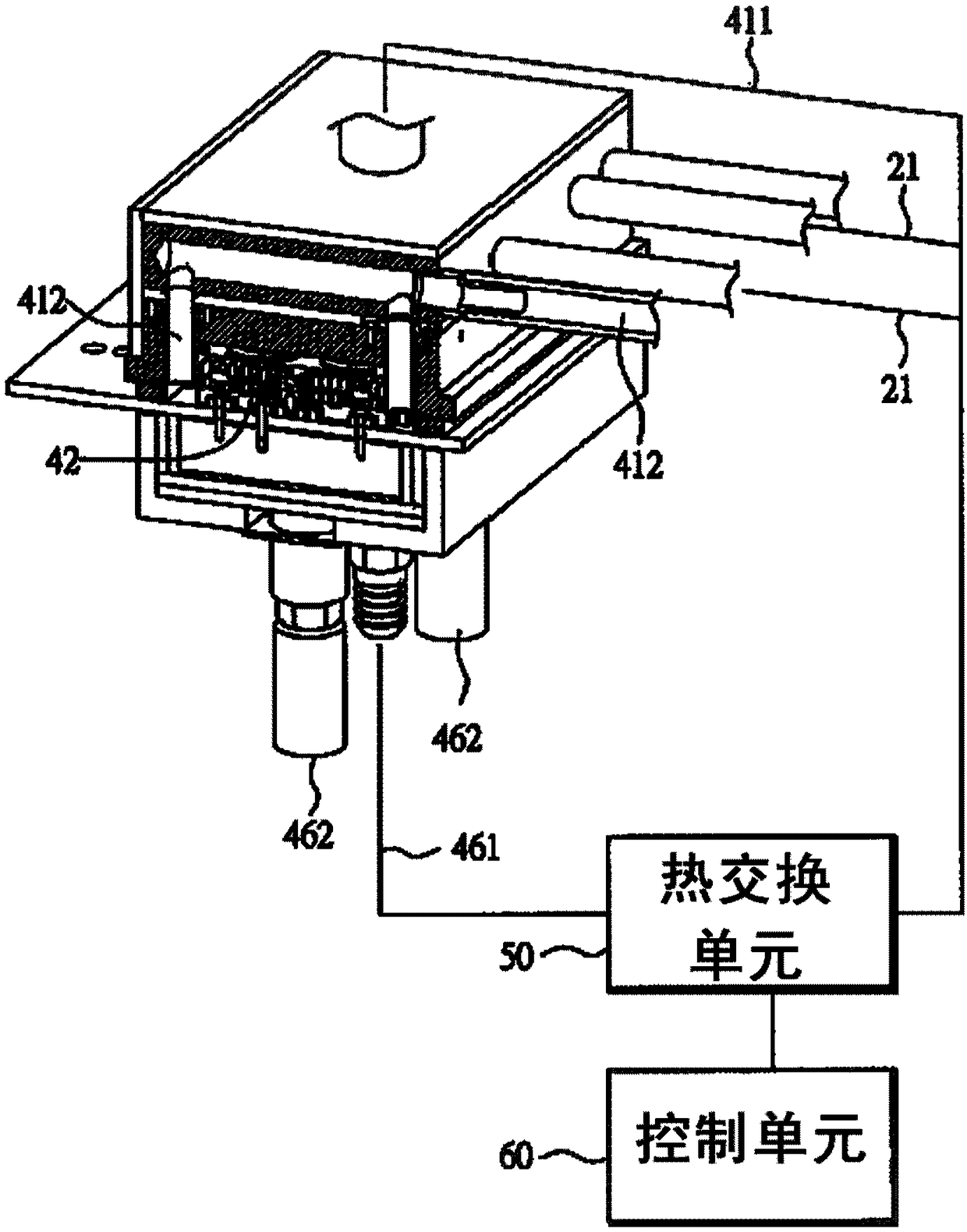
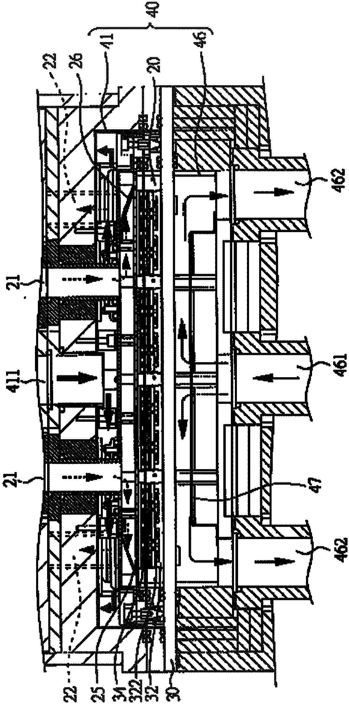
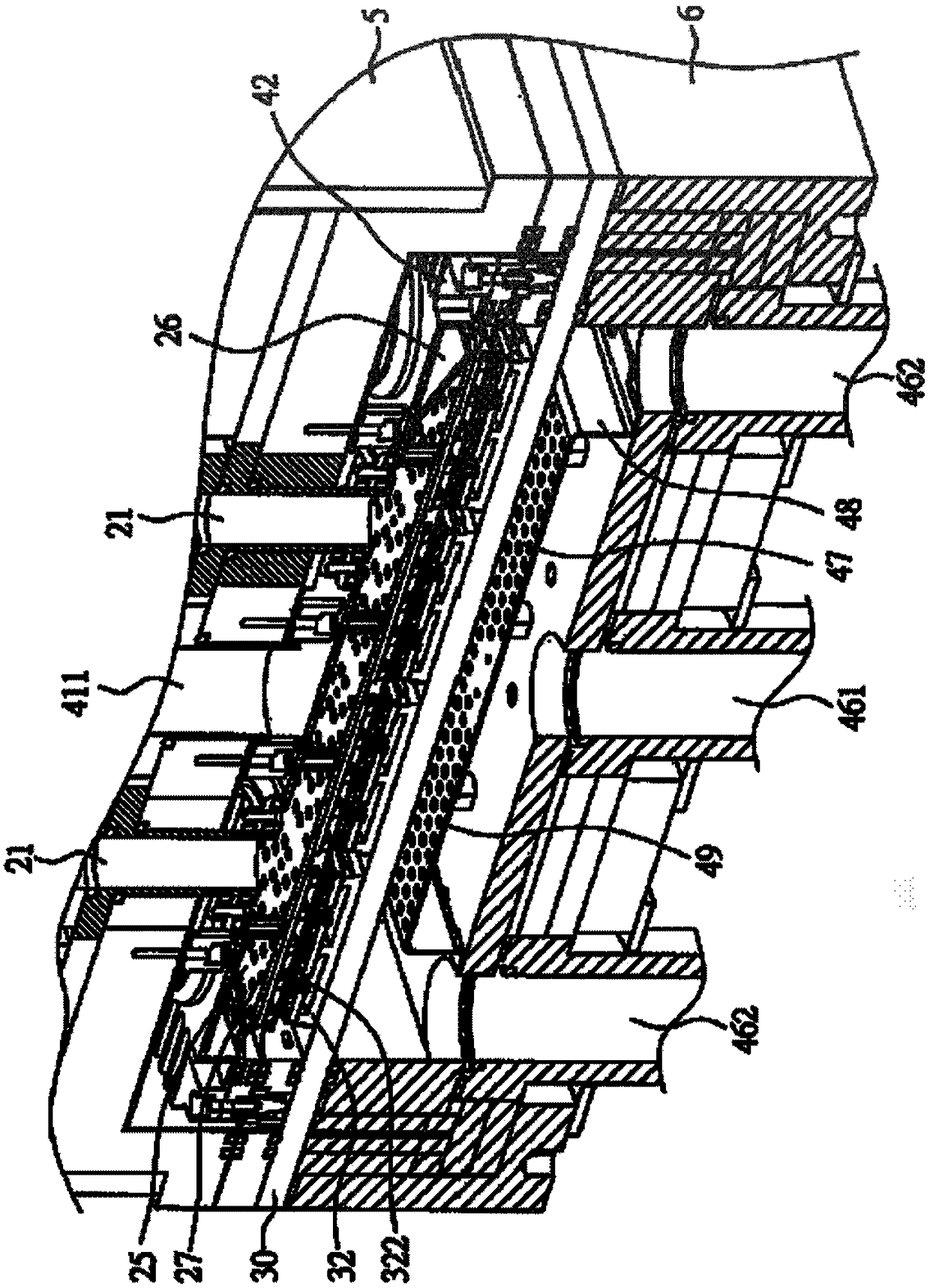
[0033] Please refer to figure 1 , figure 2 and image 3 , which are respectively a schematic diagram of a high-low temperature switching test module and two cross-sectional views from different viewing angles in a preferred embodiment of the present invention. The high and low temperature switching test module of the present embodiment includes: an inner cavity 20, an outer cavity 40 having an upper cavity 41 and a lower cavity 46, a test carrier 30, a plurality of test sockets 32, a thermal The switching unit 50 and a control unit 60 . Wherein, the test carrier board 30 is separated to form an upper cavity 41, a lower cavity 46 and an inner cavity 20, and the inner cavity 20 has at least one air intake channel 21 and at least one exhaust channel 22, and a plurality of test seats 32 are arranged on A plurality of probes 322 are pierced on the test carrier 30 for placing a plurality of chips 34 to be tested; the outer cavity 40 consisting of the upper cavity 41 and the lowe...


PUM


Abstract

The invention provides a high- and low-temperature switching test module, and the high- and low-temperature switching test module comprises an inner cavity, a test carrier plate, a plurality of test seats, an outer cavity, a heat exchange unit and a control unit. The inner cavity is provided with at least one air inlet channel and at least one air exhaust channel, the test carrier plate is disposed in the inner cavity, and the plurality of test seats are disposed on the test carrier plate and are used for placing of a plurality of chips to be tested; the outer cavity covers the upper, lower and side of the inner cavity, is provided with at least one air inlet channel and at least one air exhaust channel, and is used to heat or cool the inner cavity; the heat exchange unit is separately connected with the at least one air inlet channel of the inner cavity and the at least one air inlet channel of the outer cavity; the control unit is electrically connected to the heat exchange unit; andthe inner cavity is provided with a flow guiding cover, and the air guiding cover is provided with a plurality of flow guiding holes and is used to guide a gas provided by the heat exchange unit to heat or cool the test carrier plate. Therefore, high- and low-temperature test time of the chips to be tested can be greatly shortened, and production efficiency can be increased.

Description

technical field [0001] The invention relates to a high-low temperature switching test module, in particular to a test module suitable for rapid high-low temperature switching. Background technique [0002] At present, some electronic components or chip packages on the market, such as integrated circuits, are usually installed in the form of miniaturized electronic components such as chips in a circuit composed of several main circuit components, so as to form a continuous and complete circuit function. Among them, in order to ensure the reliability of the integrated circuit module during use, the chips installed and used in the integrated circuit module must be tested for high and low temperature before they are installed or used. That is to say, long-term high and low temperature operation of chips can accelerate the failure of chips that already have defects as soon as possible, so that defective chips can be screened out and eliminated. [0003] At present, some of the m...

Claims


Application Information

Patent Timeline
Patent Type & Authority Applications(China)
IPC IPC(8): G01R31/28
CPCG01R31/2875G01R31/2877
Inventor 詹勋亮蔡宗益张育杰
Owner KING YUAN ELECTRONICS
Learn More