
A high-precision DC variable speed constant temperature and humidity unit

A constant temperature and humidity, high-precision technology, used in heating methods, space heating and ventilation details, lighting and heating equipment, etc. Contact area, the effect of ensuring the quality of dehumidification

Active Publication Date: 2020-04-10
NANJING BOSEN TECH
View PDF2 Cites 0 Cited by
  • Summary
  • Abstract
  • Description
  • Claims
  • Application Information

AI Technical Summary

Problems solved by technology

The constant temperature and humidity unit with this structure includes fixed frequency system, frequency conversion system, centrifugal fan, humidifier, heater and evaporator, and can adjust the temperature and humidity of the compressor according to the difference between the detected temperature and humidity value and the set temperature and humidity value. Operating frequency and number of compressors, but the dehumidification mechanism of the constant temperature and humidity unit is not effective, and the Chinese utility model patent CN206420127 U discloses a constant temperature and humidity unit, the constant temperature and humidity unit of this structure can have a certain Dehumidification effect, but it is easy to reduce the dehumidification effect due to the accumulation of condensed water, which limits its scope of application

Method used


Image

  • A high-precision DC variable speed constant temperature and humidity unit
  • A high-precision DC variable speed constant temperature and humidity unit
  • A high-precision DC variable speed constant temperature and humidity unit

Examples


Embodiment Construction

[0018] The standard parts used in the present invention can be purchased from the market, and the special-shaped parts can be customized according to the instructions and the accompanying drawings. The specific connection methods of each part adopt mature bolts, rivets, welding in the prior art , pasting and other conventional means, no longer described in detail here.

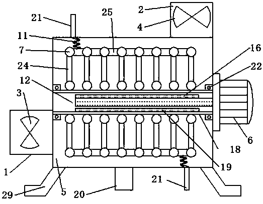
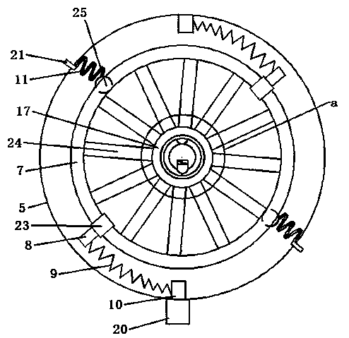
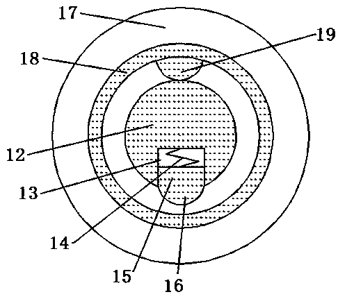
[0019] refer to Figure 1-6 A specific embodiment of the present invention includes a cylindrical barrel 5, the barrel 5 is connected with an air inlet pipe 1, an air outlet pipe 2 and two cooling water pipes 21, and a motor 6 is fixedly connected to the barrel 5. A rotating shaft 12 is fixedly connected to the motor 6, and the rotating shaft 12 is coaxial with the cylinder body 5. A cavity 13 is opened on the rotating shaft 12, and a plugboard 15 is movably inserted in the cavity 13 through several second springs 14. The inside of the cylinder 5 is also connected with a sleeve 18 through two bearings 22, the...


PUM


Abstract

The invention discloses a high-precision direct-current variable-rotating-speed constant temperature and constant humidity unit. The high-precision direct-current variable-rotating-speed constant temperature and constant humidity unit comprises a cylinder, an air inlet pipe, an air outlet pipe, cooling water pipes, a motor, a rotating shaft, an inserting plate and a sleeve. The inner side of the sleeve is fixedly connected with a blocking strip. The rotating shaft is located in the sleeve. A plurality of annular pipes are fixedly arranged on the outer side of the sleeve in a sleeving mode. Arc-shaped pipes are connected to the outer sides of the annular pipes in a penetrating mode through first metal pipes. The two ends of the two arc-shaped pipes in the same plane are connected mutually through two connectors correspondingly. The two rows of connectors are fixedly connected through two connecting plates correspondingly. The inner wall of the cylinder is further fixedly connected withfixing blocks. First springs are movably connected between the fixing blocks and the connecting plates. The two rows of arc-shaped pipes communicate mutually through two second metal pipes correspondingly. The second metal pipes are connected with spring hoses. The spring hoses are connected with the cooling water pipes in a penetrating mode. According to the high-precision direct-current variable-rotating-speed constant temperature and constant humidity unit, the defects in the prior art can be relieved, and the better dehumidification effect is achieved.

Description

technical field [0001] The invention relates to a water-cooled constant temperature and humidity unit, in particular to a high-precision DC variable speed constant temperature and humidity unit. Background technique [0002] In addition to adjusting the air temperature, the constant temperature and humidity unit also has functions such as humidity adjustment and dust removal. Compared with ordinary air conditioners, precision air conditioners with constant temperature and humidity are required to operate without stopping all year round, so their reliability is very high. There are many options for the air supply system of the constant temperature and humidity machine. Chinese utility model patent CN 205090679 U discloses a DC frequency conversion water-cooled high-precision constant temperature and humidity unit. The constant temperature and humidity unit with this structure includes fixed frequency system, frequency conversion system, centrifugal fan, humidifier, heater a...

Claims


Application Information

Patent Timeline
Patent Type & Authority Patents(China)
IPC IPC(8): F24F1/02F24F3/14F24F13/32
CPCF24F1/02F24F3/14F24F13/32
Inventor 李颖徐元平盛伟
Owner NANJING BOSEN TECH
Learn More