
Organic light emitting diode (OLED) pixel drive circuit and OLED display

A pixel drive circuit and capacitor technology, applied in static indicators, instruments, etc., can solve problems such as decreased luminous efficiency, prone to afterimages on the display screen, and biased luminous characteristics, so as to avoid offset, improve display effect, and eliminate The effect of afterimage phenomenon

Active Publication Date: 2018-11-30
WUHAN CHINA STAR OPTOELECTRONICS SEMICON DISPLAY TECH CO LTD
View PDF13 Cites 11 Cited by
  • Summary
  • Abstract
  • Description
  • Claims
  • Application Information

AI Technical Summary

Problems solved by technology

[0003] However, due to the long-term display of the same brightness of the existing organic light-emitting diodes, its luminous characteristics are biased, and the luminous efficiency is reduced, which makes the display screen prone to image sticking and reduces the display effect.

Method used


Image

  • Organic light emitting diode (OLED) pixel drive circuit and OLED display
  • Organic light emitting diode (OLED) pixel drive circuit and OLED display
  • Organic light emitting diode (OLED) pixel drive circuit and OLED display

Examples


Embodiment Construction

[0036] The following descriptions of the various embodiments refer to the accompanying drawings to illustrate specific embodiments in which the present invention can be practiced. The directional terms mentioned in the present invention, such as "up", "down", "front", "back", "left", "right", "inside", "outside", "side", etc., are for reference only The orientation of the attached schema. Therefore, the directional terms used are used to illustrate and understand the present invention, but not to limit the present invention. In the figures, structurally similar units are denoted by the same reference numerals.

[0037] The traditional OLED pixel drive circuit is usually 2T1C, that is, the structure of two thin film transistors plus a capacitor, which converts voltage into current.

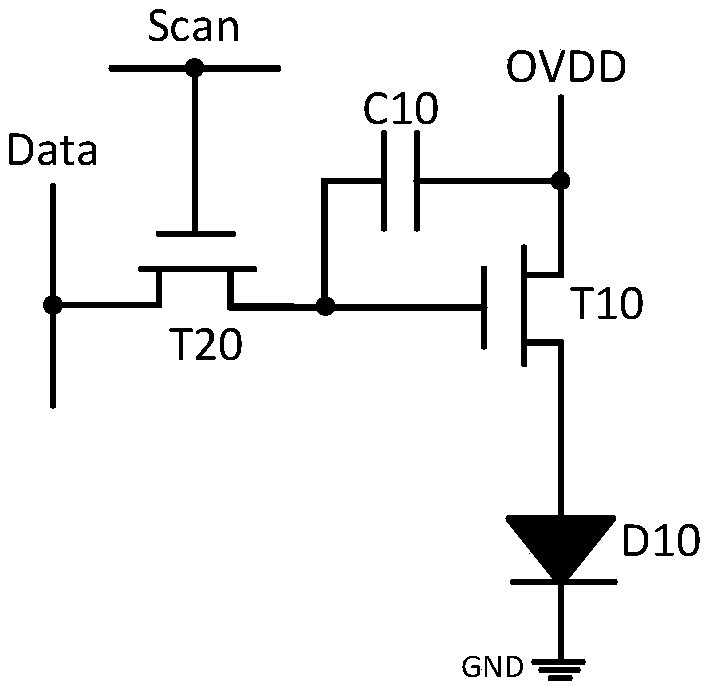
[0038] like figure 1 As shown, the existing 2T1C OLED pixel driving circuit includes a first thin film transistor T10, a second thin film transistor T20, a capacitor C10 and an organic light emi...


PUM


Abstract

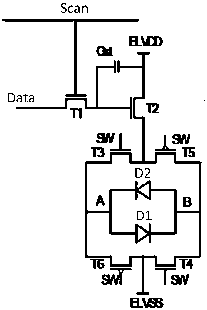
The invention provides an organic light emitting diode (OLED) pixel drive circuit and an OLED display. According to the OLED pixel drive circuit, a drain electrode of a second thin film transistor isconnected with a source electrode of a third thin film transistor and a source electrode of a fifth thin film transistor, control signals are connected into a grid electrode of the third thin film transistor, a grid electrode of a fourth thin film transistor, a grid electrode of the fifth thin film transistor and a grid electrode of a sixth thin film transistor, and a drain electrode of the thirdthin film transistor is connected with a positive electrode of a first OLED, a negative electrode of a second OLED and a source electrode of the sixth thin film transistor; and a drain electrode of the fifth thin film transistor is connected with a negative electrode of the first OLED, a positive electrode of the second OLED and a source electrode of the fourth thin film transistor. According to the OLED pixel drive circuit and the OLED display, sticking images can be eliminated, and the display effect is improved.

Description

【Technical field】 [0001] The invention relates to the field of display technology, in particular to an OLED pixel drive circuit and an OLED display. 【Background technique】 [0002] Active-matrix organic light emitting diode (AMOLED, Active-matrix organic light emitting diode) is a display technology used in TVs and mobile devices. Compared with the existing mainstream liquid crystal displays, AMOLED has high contrast, wide viewing angle, Low power consumption, thinner volume and other advantages are currently one of the most concerned technologies in flat panel display technology. [0003] However, because the existing organic light emitting diodes display the same brightness for a long time, the luminous characteristics are biased, and the luminous efficiency is reduced, which makes the display screen prone to image sticking and reduces the display effect. [0004] Therefore, it is necessary to provide an OLED pixel driving circuit and an OLED display to solve the problems...

Claims


Application Information

Patent Timeline
Patent Type & Authority Applications(China)
IPC IPC(8): G09G3/3233G09G3/3266
CPCG09G3/3233G09G3/3266G09G2320/0257G09G2300/0819G09G2300/0823G09G2300/0842G09G2310/0256G09G2320/043G09G3/2007G09G3/3258
Inventor 颜伟男李骏
Owner WUHAN CHINA STAR OPTOELECTRONICS SEMICON DISPLAY TECH CO LTD
Learn More