
Pull wire manufacturing device

A device and wire gripper technology, which is applied in the field of wire-pulling equipment, can solve the problems of reduced work efficiency of operators, inability to determine the distance between binding wires, and non-compliance with construction standards, etc., and achieves easy size control, automation, and reduced work intensity. Effect

Pending Publication Date: 2018-11-30
CREC RAILWAY WUHAN ELECTRIFICATION BUREAU GRP GUANGZHOU BRANCH
View PDF8 Cites 2 Cited by
  • Summary
  • Abstract
  • Description
  • Claims
  • Application Information

AI Technical Summary

Problems solved by technology

In actual operation, it is impossible to determine the spacing of the binding wires, which may easily cause the spacing of the winding binding wires to be different, that is, the spacing of the binding wires may be too long or too short, the product is neither beautiful nor meets the construction standards, and the work of the operators Efficiency will be significantly reduced with the increase of labor intensity, time-consuming and labor-intensive

Method used


Image

  • Pull wire manufacturing device
  • Pull wire manufacturing device
  • Pull wire manufacturing device

Examples


Embodiment Construction

[0026] In order to make the purpose, technical solutions and advantages of the embodiments of the present invention clearer, the technical solutions in the embodiments of the present invention will be clearly and completely described below in conjunction with the drawings in the embodiments of the present invention. Obviously, the described embodiments It is a part of embodiments of the present invention, but not all embodiments. The components of the embodiments of the invention generally described and illustrated in the figures herein may be arranged and designed in a variety of different configurations.

[0027] Accordingly, the following detailed description of the embodiments of the invention provided in the accompanying drawings is not intended to limit the scope of the claimed invention, but merely represents selected embodiments of the invention. Based on the embodiments of the present invention, all other embodiments obtained by persons of ordinary skill in the art wi...


PUM


Abstract

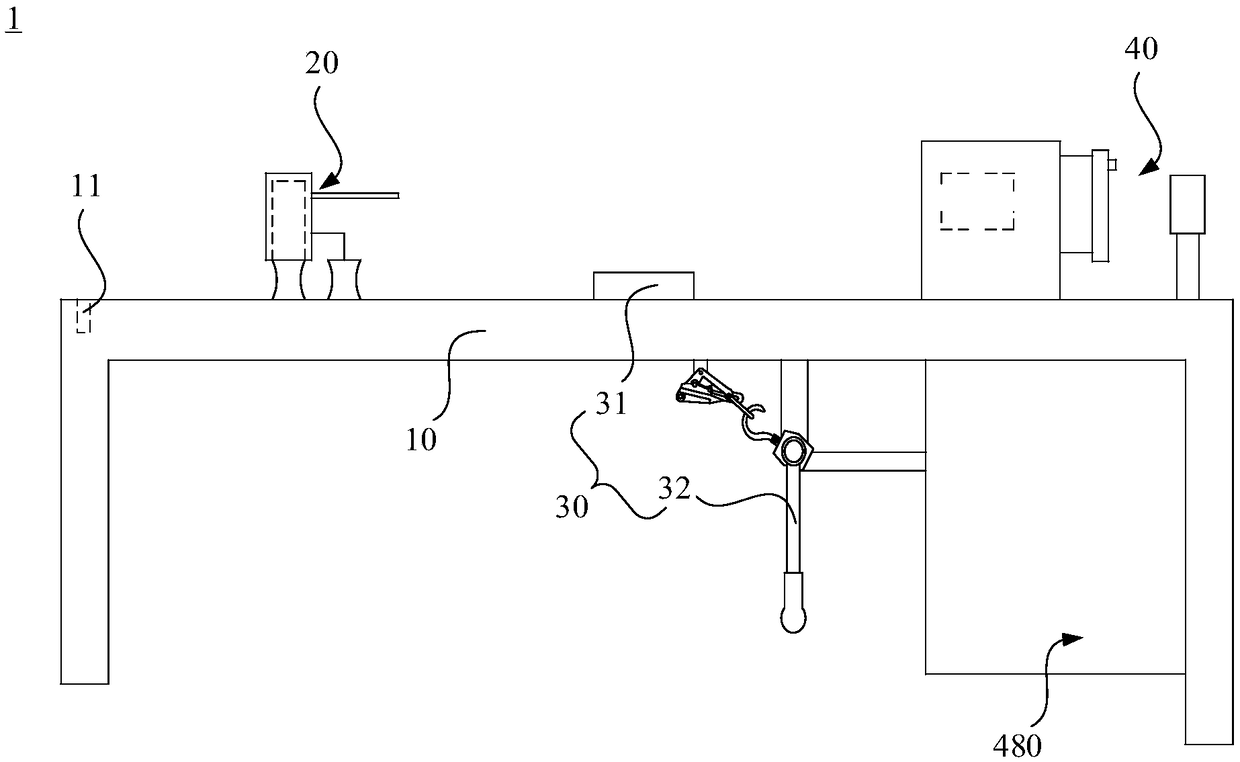
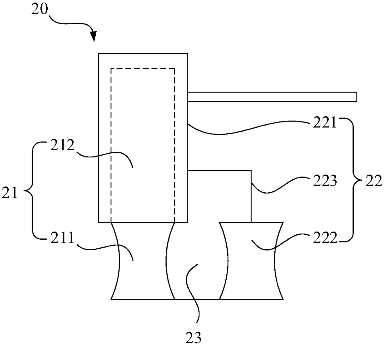
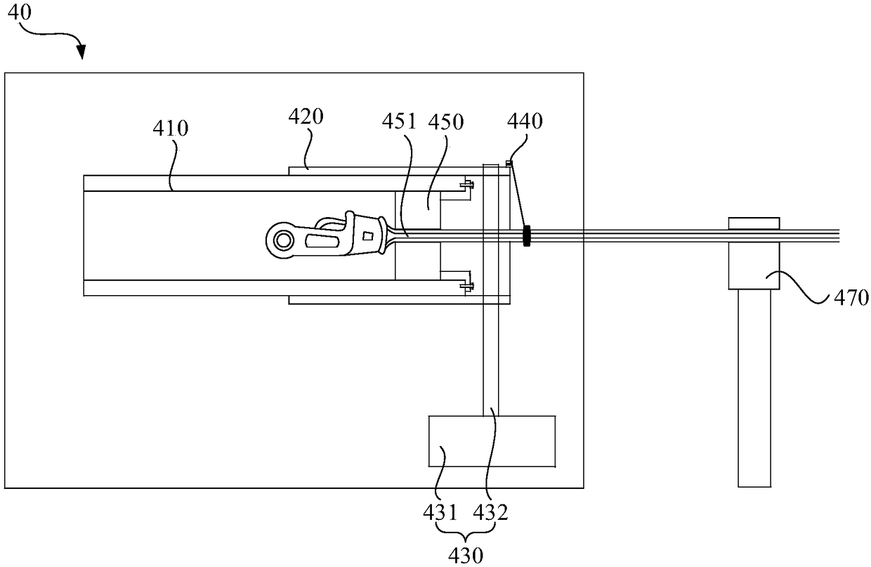
A pull wire manufacturing device comprises an installation base, a bending device, a tightening device and a winding device. The installation base is provided with fixed holes. The bending device comprises a first mold and a second mold, the first mold comprises a first rotating block and a connecting column, the connecting column is fixedly connected to the first rotating block; the second mold comprises a cylinder body and a second rotating block, the cylinder body is connected to the second rotating block through a connecting piece, the cylinder body is movably sleeved on the outside of theconnecting column, and the first rotating block and the second rotating block are separated by a clamping gap. The tightening device comprises a wire gripper and a force applying device, and the wiregripper is connected to the force applying device. The winding device comprises an inner sleeve, an outer sleeve and a driving device. The outer sleeve is connected to the outside of the inner sleevein a sleeving mode, the outer sleeve and the inner sleeve are connected by thread to realize rotation , and the inner sleeve is provided with a holding and clamping device. The driving device is usedfor driving the outer sleeve to rotate, the winding device further comprises a fixing seat, and the fixing seat is provided with a limiting groove for fixing the binding place of the cable.

Description

technical field [0001] The invention relates to the field of wire drawing processing equipment, in particular to a wire drawing manufacturing equipment. Background technique [0002] The stay wire is used to connect the ground and the tower, and then form an effective traction and fixation to the tower. At the connection between the guy wire and the ground, it is necessary to bend the front end of the guy wire to the main guy wire, insert and fix the bent part of the guy wire into the wedge-shaped clamp, and then use a soft steel wire to wind the part bent to the main guy wire and the main guy wire. [0003] In the prior art, it is generally relied on operators to manually bend and shape the pull wires. However, in actual operation, due to the high rigidity of the cable, the operator needs a lot of force to bend the cable multiple times, which makes the bending efficiency of the cable very low, and it is not easy to control the size during operation. The wedge-shaped clamp...

Claims


Application Information

Patent Timeline
Patent Type & Authority Applications(China)
IPC IPC(8): E04H12/20
CPCE04H12/20
Inventor 陈伟
Owner CREC RAILWAY WUHAN ELECTRIFICATION BUREAU GRP GUANGZHOU BRANCH
Learn More