
Electric pole with rooting-into-soil function

An electric pole and function technology, applied in the field of electric poles with functions of burying and rooting in the soil, can solve the problems of life safety threats of maintenance personnel, broken cables, and loose electric poles, etc., and achieves enhanced stability, improved locking force, and increased lock Tightening effect

Active Publication Date: 2018-11-30
STATE GRID HEBEI ELECTRIC POWER CO LTD +1
View PDF6 Cites 6 Cited by
  • Summary
  • Abstract
  • Description
  • Claims
  • Application Information

AI Technical Summary

Problems solved by technology

[0003] The burial of the poles is generally done after digging and filling, or the bottom is fixed in the soil in the form of a cement seat. Since the poles are longer above the ground, they will bear the pressure of the cables for a long time, and electricians will also increase the poles during maintenance. The force of the pole, and the force of the pole cannot be uniform in all directions, so it is in a biased force for a long time. When encountering extreme weather such as strong winds, as the cable shakes, the pole shakes, which is inevitable. If the pole is loose, electricians are often required to repair cables and other power components after extreme weather. If the pole is unstable at this time, it will not only cause the pole to fall and break the cable, but also pose a great threat to the life safety of the maintenance personnel.

Method used


Image

  • Electric pole with rooting-into-soil function
  • Electric pole with rooting-into-soil function

Examples


Embodiment Construction

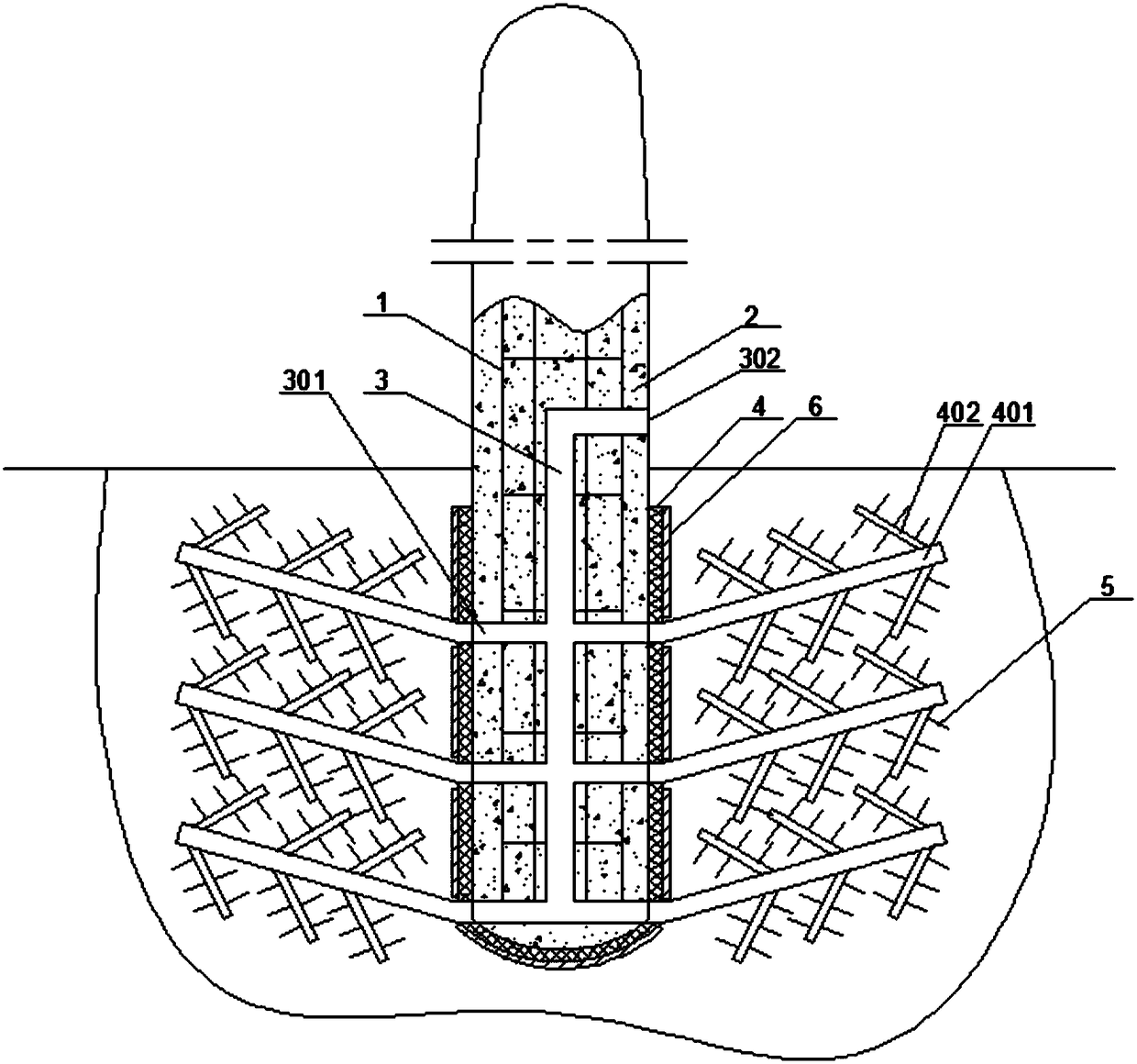
[0015] The invention relates to an electric pole with the function of rooting into the soil, including a steel frame 1 and concrete 2 on the outside. The lower end of the electric pole is provided with an inflatable pipeline 3 inside, and the output ends of the inflatable pipeline 3 are distributed in a group. There is an air outlet 301 on the outer surface of the electric pole, and the input end is an air inlet 302 above the ground level. The lower end of the electric pole is fitted with a rubber sleeve 4 from the bottom up, and the outer circumference of the rubber sleeve 4 is provided with an air outlet 301 A group of airbags in one-to-one correspondence, the airbags include a main airbag 401 and a branch airbag 402 on its outer circumference.

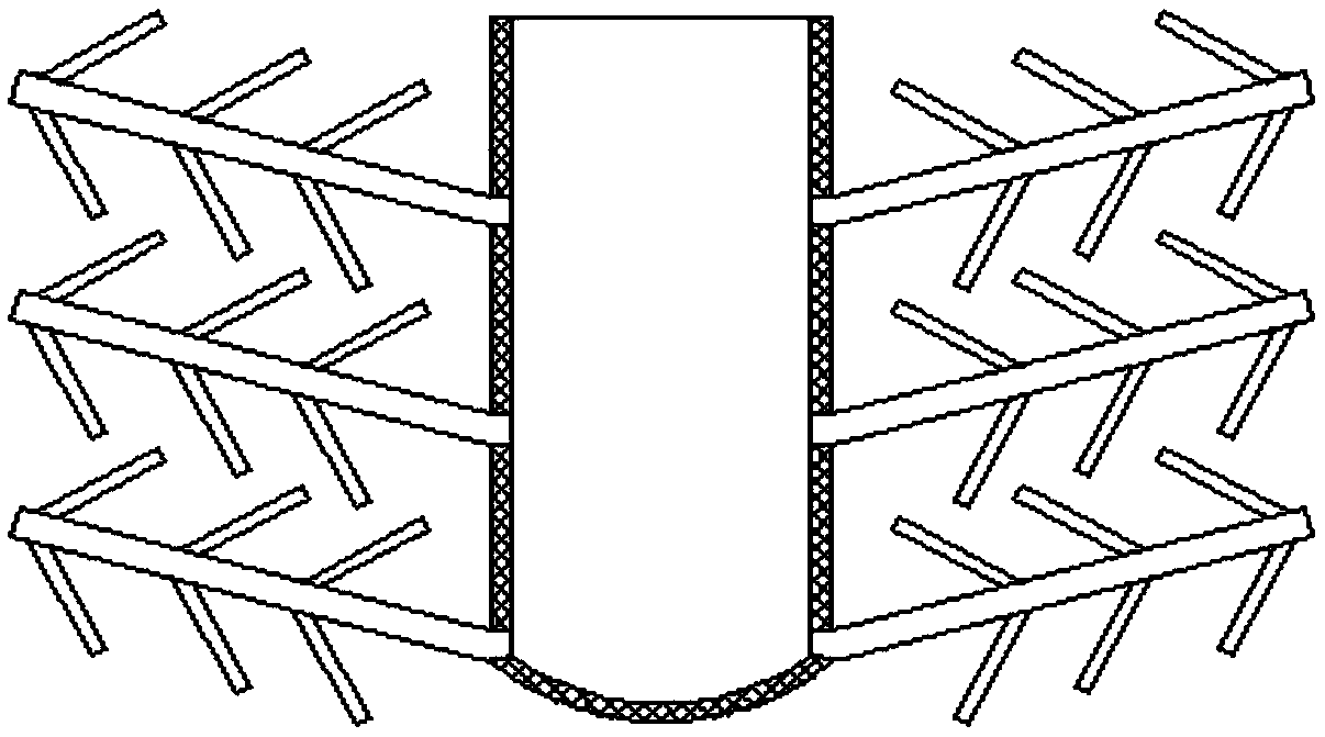
[0016] Specific examples, such as figure 1 and figure 2 As shown, first put the rubber sleeve 4 into the lower part of the electric pole from the bottom, and all the air bags correspond to the air outlet holes 301 one by one, and ...


PUM


Abstract

The invention relates to an electric pole with a rooting-into-soil function. The electric pole comprises a steel skeleton and external concrete thereof. An inflation pipeline is arranged in the lowerend of the electric pole, a group of air outlet holes distributed in the outer circumferential surface of the electric pole is formed in the output end of the inflation pipeline, and air inlet holes located above the ground plane is formed in the input end of the inflation pipeline. The lower end of the electric pole is sleeved with a rubber sleeve from bottom to top, a group of airbags corresponding to the air outlet holes is arranged on the outer circumference of the rubber sleeve, and the airbags include main airbag bodies and branch airbag bodies on the outer circumferences of the main airbag bodies. According to the electric pole with the rooting-into-soil function, a root shape is formed by inflation of the airbags, and the airbags are deflated after being embedded, so that the airbags have a downward pulling force on the electric pole; and therefore the electric pole has the ability to be rooted in the soil, the grasping force of the electric pole in the soil is greatly improved, and the safety and stability are significantly improved.

Description

technical field [0001] The invention belongs to the technical field of electric equipment, and in particular relates to an electric pole with the function of rooting into the soil. Background technique [0002] As a supporting device for erecting wires, electric poles are widely used in the electric power industry. Electric poles are installed in rural areas and most urban areas. Most of the electric poles are formed by internal steel skeleton and external concrete pouring. [0003] The burial of the poles is generally done after digging a pit, or fixed in the soil by setting a cement seat at the bottom. Since the poles are longer above the ground, they will bear the pressure of the cables for a long time, and electricians will also increase the poles during maintenance. The force of the pole, and the force of the pole can not be uniform in all directions, so it is in a biased force for a long time. When encountering extreme weather such as strong winds, as the cable shakes,...

Claims


Application Information

Patent Timeline
Patent Type & Authority Applications(China)
IPC IPC(8): E04H12/00E04H12/22
CPCE04H12/00E04H12/22E04H12/2215
Inventor 杜明明许春光安少聪杜洁吴灏曹星何延强
Owner STATE GRID HEBEI ELECTRIC POWER CO LTD
Learn More