Combined-type grouting sleeve connecting structure and steel bar connecting construction method

A technology for grouting sleeves and connecting structures, applied in structural elements, building components, building structures, etc., can solve problems such as large operating space and post-casting area, affecting the integrity of prefabricated components, and achieve improved quality and seismic performance. Reduce construction difficulty, increase the effect of mechanical bite and friction

Active Publication Date: 2018-11-30
NORTHWEST UNIVERSITY FOR NATIONALITIES +1
View PDF6 Cites 7 Cited by
  • Summary
  • Abstract
  • Description
  • Claims
  • Application Information

AI Technical Summary

Problems solved by technology

[0003] In view of this, the purpose of the present invention is to provide a combined grouting sleeve connection structure and a steel bar connection construction method to solve the problem that the upper operating space and the post-casting area of ​​the prefabricated component are relatively large, which affects the integrity of the prefabricated component, so that the force of the structure There are more and more reliable transmission forms, which can reduce the difficulty of construction, improve construction efficiency, and improve the overall quality and seismic performance of prefabricated components.

Method used


Image

  • Combined-type grouting sleeve connecting structure and steel bar connecting construction method
  • Combined-type grouting sleeve connecting structure and steel bar connecting construction method
  • Combined-type grouting sleeve connecting structure and steel bar connecting construction method

Examples


Embodiment Construction

[0033] The preferred embodiments of the present invention will be described in detail below with reference to the accompanying drawings.

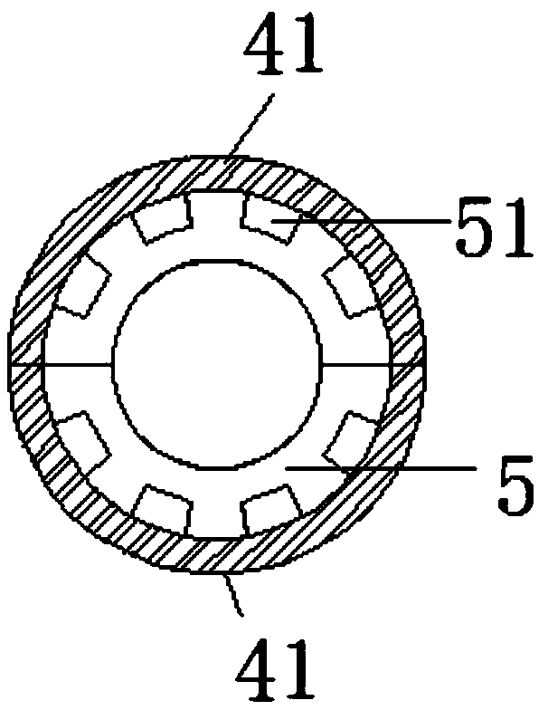
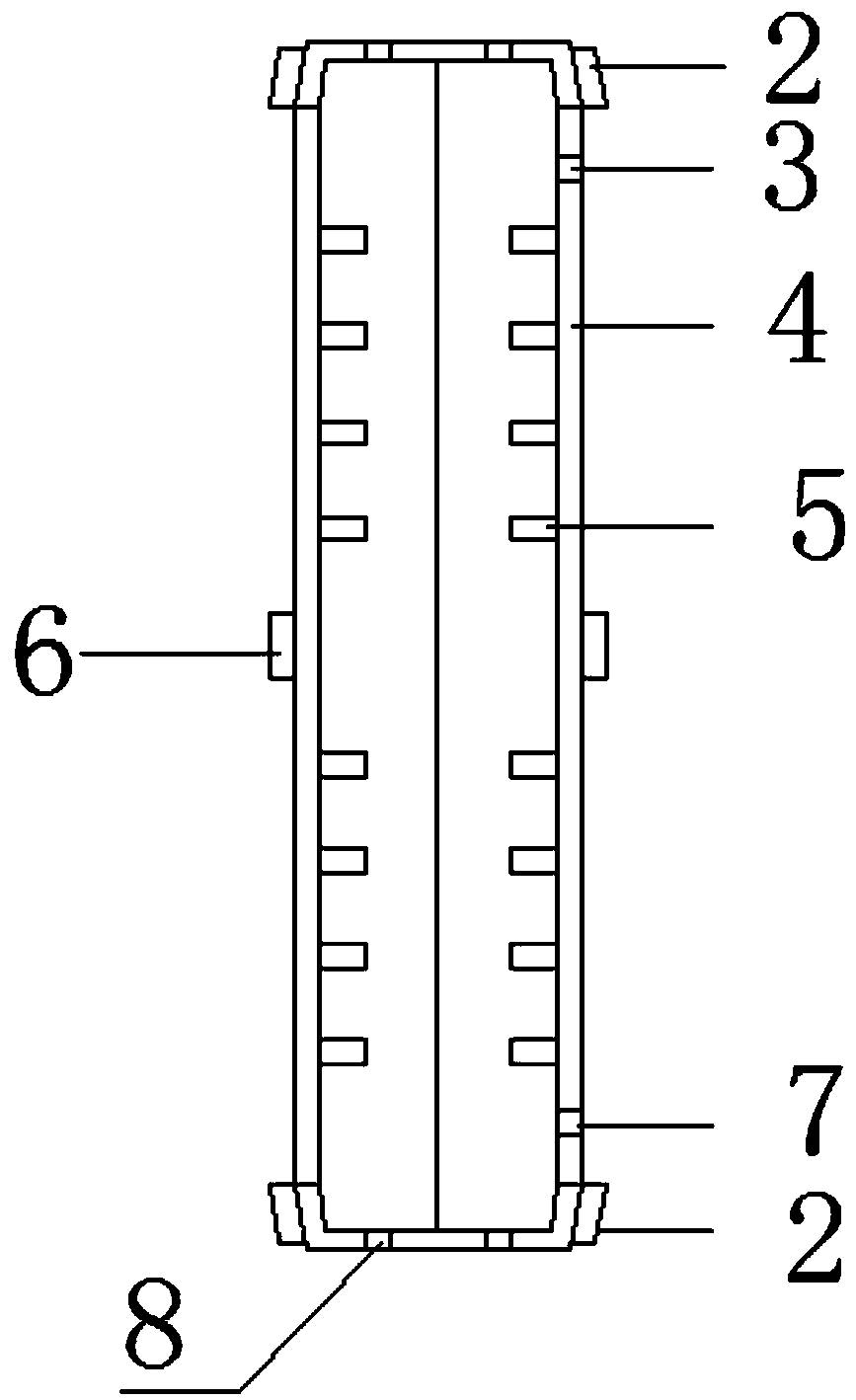
[0034] see Figure 1-3, the combined grouting sleeve connection structure of a specific embodiment, including a sleeve body 4, the sleeve body 4 is a vertical cylinder, along the axial direction of the sleeve body 4, on the side of the sleeve body 4 The inner wall is provided with several protruding annular inner ribs 5 at intervals. The cross-section of the annular inner ribs 5 is rectangular. Rib holes 51 to ensure the fluidity of grouting, the rib holes 51 are several spaced apart along the circumferential direction of the annular inner rib 5; the lower end of the sleeve body 4 is provided with a grouting hole 7 that runs through its side wall, There is a grout hole 3 running through its side wall, the grout hole 7 and the grout hole 3 have the same direction and are opened on the same side, so that the grouting and plugging of the grou...


PUM


Abstract

The invention discloses a combined-type grouting sleeve connecting structure and a steel bar connecting construction method. The combined-type grouting sleeve connecting structure comprises a verticalsleeve body; an upper steel bar and a lower steel bar are inserted from the two ends of the sleeve body correspondingly; a plurality of bulged annular inner ribs are arranged on the inner wall of thesleeve body in the axial direction at intervals; a grouting hole and a slurry discharging hole which penetrate through the sleeve body are formed in the upper end and the lower end of the sleeve body; the ends, in the sleeve body, of the upper steel bar and the lower steel bar are connected with horizontal end plates correspondingly, and the diameter of the end plates is larger than the inner diameter of the annular inner ribs; the two end plates are located between any two of the adjacent annular inner ribs; and the sleeve body is of a two-half separable structure split by the plane passingthrough the axis of the sleeve body, and a constraint part is arranged on the outer side of the sleeve body, so that the sleeve body of the two-half separable structure keeps in the grouting use overall state. The grouting sleeve connecting structure adopts separating design, the integrity of a prefabricated part can be improved, and thus the quality and seismic performance are improved; and partsof processes are adjusted, the construction difficulty is lowered, and the efficiency is improved.

Description

technical field [0001] The invention belongs to the technical field of fixed buildings, and in particular relates to a combined grouting sleeve connection structure and a steel bar connection construction method. Background technique [0002] Prefabricated building is an energy-saving, environmentally friendly and efficient building form. Prefabricated concrete components have the advantages of high economic benefits, less impact on construction by climatic conditions, easy guarantee of product quality, short construction time and less environmental pollution, and have become an important direction for the development of the construction industry. With the development of prefabricated buildings, there are still many problems to be solved. Among them, the connection of steel bars is the key technology for the development of prefabricated structures. At present, the steel bars are mainly connected by grouting sleeves in the construction process, and the grouting sleeves with s...

Claims


Application Information

Patent Timeline
Patent Type & Authority Applications(China)
IPC IPC(8): E04C5/16E04G21/12
CPCE04C5/165E04G21/12Y02E10/72
Inventor 吴忠铁范萍萍
Owner NORTHWEST UNIVERSITY FOR NATIONALITIES
Why Eureka
Try Eureka