
Aerial work conveying scaling ladder device

A high-altitude operation and aerial ladder technology, applied in the direction of lifting devices, can solve the problems that cannot meet the basic requirements of high-altitude operations, cannot guarantee the accuracy of aerial ladder lifting, and affect the personal safety of staff, so as to improve the use of aerial ladders. The effect of saving the number of drives and a high degree of mechanical automation

Active Publication Date: 2018-11-30
ELECTRIC POWER RES INST OF GUANGXI POWER GRID CO LTD
View PDF5 Cites 1 Cited by
  • Summary
  • Abstract
  • Description
  • Claims
  • Application Information

AI Technical Summary

Problems solved by technology

[0002] Existing observation platforms for high-altitude operations, especially high-altitude aerial ladders used for high-altitude monitoring, lookout monitoring, etc., are often slow and inefficient when they are raised, and the accuracy of the aerial work cannot be guaranteed or due to materials and structural limitations. The height is generally low and takes up a lot of space. In some special environments, it has a certain impact on the personal safety of the staff, and cannot well meet the basic requirements of high-altitude operations.

Method used


Image

  • Aerial work conveying scaling ladder device
  • Aerial work conveying scaling ladder device
  • Aerial work conveying scaling ladder device

Examples


Embodiment Construction

[0027] The following will clearly and completely describe the technical solutions in the embodiments of the present invention with reference to the drawings in the embodiments of the present invention. Apparently, the described embodiments are only some of the embodiments of the present invention, but not all of them. Based on the embodiments of the present invention, all other embodiments obtained by persons of ordinary skill in the art without creative efforts fall within the protection scope of the present invention.

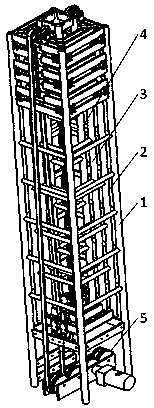
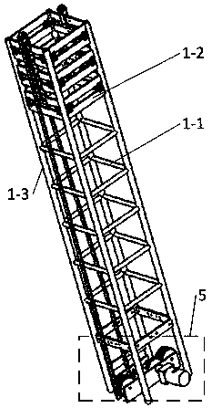
[0028] Please refer to figure 1 , The preferred embodiment of the present invention provides an aerial work conveying aerial ladder device, including an aerial ladder mechanism and an aerial ladder driving mechanism.

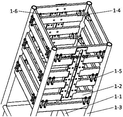
[0029] The aerial ladder mechanism includes a first-level aerial ladder 1, a second-level aerial ladder 2, a third-level aerial ladder 3 and a fourth-level aerial ladder 4, the first-level aerial ladder 1 is located at the bottom, the second-l...


PUM


Abstract

The invention discloses an aerial work conveying scaling ladder device. The aerial work conveying scaling ladder device comprises a scaling ladder mechanism and a scaling ladder driving mechanism. Thescaling ladder mechanism comprises a first-level scaling ladder, a second-level scaling ladder, a third-level scaling ladder and a fourth-level scaling ladder, wherein the first-level scaling ladder,the second-level scaling ladder, the third-level scaling ladder and the fourth-level scaling ladder are sequentially arranged in a sleeving manner. The scaling ladder driving mechanism is arranged onthe lower portion of the first-level scaling ladder. The scaling ladder mechanism is internally provided with multiple rolling wheel devices and scaling ladder hanging plates. The hanger plate hanging plates are provided with cover sleeves and rope steel rings. Transmission is achieved between the first-level scaling ladder and the second-level scaling ladder through a synchronous belt. Transmission is achieved between the second-level scaling ladder and the third-level scaling ladder as well as between the third-level scaling ladder and the fourth-level scaling ladder through flexible transmission ropes. According to the aerial work conveying scaling ladder device, the whole ascending and descending process of a scaling ladder is completed through the driving mechanism; the mechanical automation degree is high; the device is easy to operate and good in precision, the operation speed of the scaling ladder can be guaranteed, and the using efficiency of the scaling ladder is improved; amulti-level linkage ascending-and-descending structure is adopted, and the drive number and the space occupied by the scaling ladder are reduced; and long-distance linear motion is achieved so that the operation height requirement can be met.

Description

technical field [0001] The invention relates to the technical field of aerial work equipment, in particular to a conveying ladder device for aerial work. Background technique [0002] Existing observation platforms for high-altitude operations, especially high-altitude aerial ladders used for high-altitude monitoring, lookout monitoring, etc., are often slow and inefficient when they are raised, and the accuracy of the aerial work cannot be guaranteed or due to materials and structural limitations. The height is generally low and takes up a lot of space. In some special environments, it has a certain impact on the personal safety of the staff, and cannot well meet the basic requirements of high-altitude operations. Contents of the invention [0003] In view of the above deficiencies, the present invention provides a conveying ladder device for aerial work. [0004] To achieve the above object, the present invention adopts the following technical solutions: [0005] An ae...

Claims


Application Information

Patent Timeline
Patent Type & Authority Applications(China)
IPC IPC(8): B66F11/00B66F13/00
CPCB66F11/00B66F13/00
Inventor 郭丽娟唐彬陈梁远谢植飚黄升平
Owner ELECTRIC POWER RES INST OF GUANGXI POWER GRID CO LTD
Learn More