
Large-capacity card storage equipment

A storage device and high-capacity technology, which is applied to conveyors, mechanical conveyors, conveyor objects, etc., can solve the problem of increasing the length of the carousel card storage device, inconvenient placement of the carousel card storage device, and inability to rationally utilize the space of the handling device. and other problems, to achieve the effect of improving the handling efficiency, reducing the length change and reducing the handling stroke.

Pending Publication Date: 2018-11-30
GUANGZHOU MINGSEN TECH CO LTD
View PDF7 Cites 0 Cited by
  • Summary
  • Abstract
  • Description
  • Claims
  • Application Information

AI Technical Summary

Problems solved by technology

[0003] However, in the above-mentioned carousel type card storage equipment, since the conveying device realizes the conveyance of the card by clamping, the card issuing device must be located on the same side of the conveying device as the card storage device, so that the conveying mechanism can drive the card clamping mechanism to move the card issuing device The sent cards are transported to the card storage slot of the turntable, which makes it impossible for the turntable card storage device to make reasonable use of the space on both sides of the transport device, thus making it inconvenient to increase the card storage capacity of the card storage device. If the card storage capacity of the device is limited, it is necessary to expand the card storage device or add multiple card storage devices on the same side of the card issuing device, which will cause the length of the carousel card storage device to increase, so that the carousel card storage The placement of equipment is particularly inconvenient

Method used


Image

  • Large-capacity card storage equipment
  • Large-capacity card storage equipment
  • Large-capacity card storage equipment

Examples


Embodiment Construction

[0027] The present invention will be further described in detail below in conjunction with the embodiments and the accompanying drawings, but the embodiments of the present invention are not limited thereto.

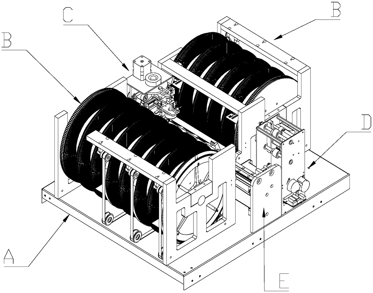
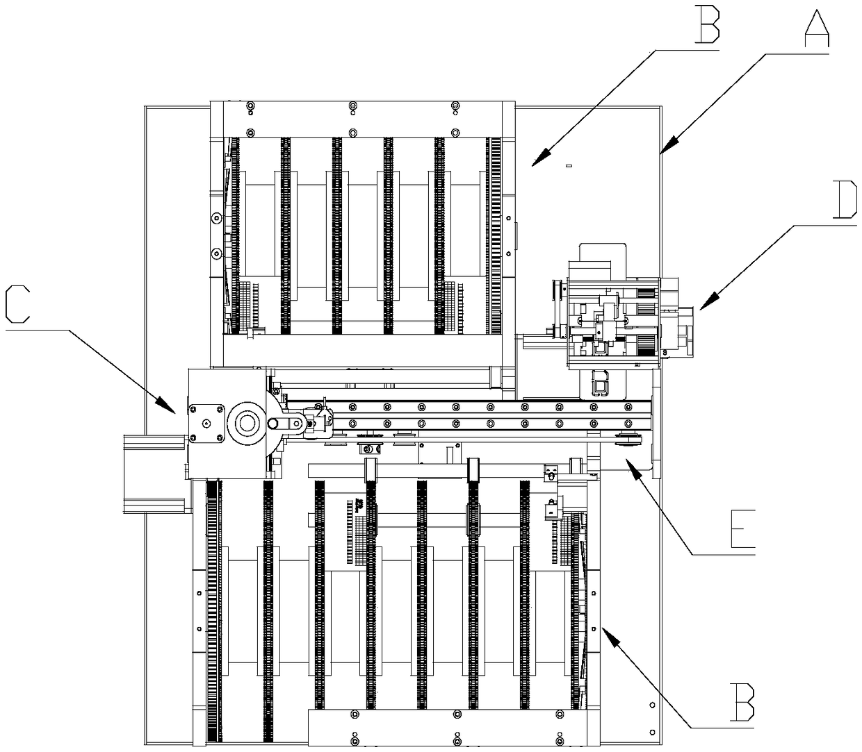
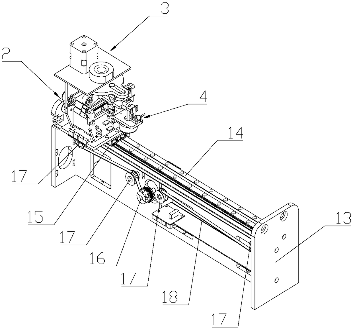
[0028] see Figure 1-Figure 12 The large-capacity card storage device of the present invention includes a frame A, a card issuing device (not shown in the accompanying drawings) arranged on the frame A, several card storage devices B, and the cards sent by the card issuing device are transported to The conveying device in the card storage device B, wherein the several card storage devices B are arranged on both sides of the conveying device, and the card issuing device is arranged on one or both sides of the conveying device; The device includes a card clamping trolley C and a trolley driving mechanism E for driving the card clamping trolley C to move between the card issuing device and the card storage device.

[0029] There are two card storage devices B in this embod...


PUM


Abstract

The invention discloses large-capacity card storage equipment. The large-capacity card storage equipment comprises card sending devices, multiple card storage devices and a carrying device. The multiple card storage devices are arranged on two sides of the carrying device. The card sending devices are arranged on one side or two sides of the carrying device. The carrying device comprises a card clamping trolley and a trolley driving mechanism. The card clamping trolley comprises a trolley frame, a card clamping mechanism and a transverse driving mechanism. The card clamping mechanism comprisesa clamping part and a clamping driving mechanism used for driving the clamping part to open and close. Two ends of the clamping part are both equipped with clamping portions. The card clamping mechanism also comprises a conveying mechanism. With the large-capacity card storage equipment, spaces on two sides of the carrying device are reasonably utilized. While the card-storage capacity is added,the large-capacity card storage equipment is convenient to place because of small changes in length of the large-capacity card storage equipment.

Description

technical field [0001] The invention relates to a card receiving machine, in particular to a large-capacity card storage device. Background technique [0002] With the development of social economy, cards have been widely used. Cards can be divided into general-purpose cards and exclusive cards. General-purpose cards can be distributed to unspecified users. Such cards are usually made uniformly by the card-making unit, and then distributed to specific users through purchase or free delivery. The exclusive card is made for specific users, and personalized information is entered in the card. After the exclusive card is made, it needs to be distributed to specific users. The distribution of traditional exclusive cards is usually picked up by the user at the designated place of the card issuer and distributed manually. The disadvantage is that a dedicated staff is required to be responsible for the card issuance, and the card is also subject to the issuer's location and card is...

Claims


Application Information

Patent Timeline
Patent Type & Authority Applications(China)
IPC IPC(8): B65G47/90B65G35/00
CPCB65G35/00B65G47/90
Inventor 夏新辉王开来李南彪徐飞吴伟文赖汉进黄文豪
Owner GUANGZHOU MINGSEN TECH CO LTD
Learn More