
Nuclear power pipeline branch pipe opening welding mould

A technology for welding molds and pipes, applied in welding equipment, auxiliary welding equipment, welding/cutting auxiliary equipment, etc., can solve the problems of heavy preparation work, high difficulty, and low welding efficiency, and achieve small preparation work and low difficulty , The effect of improving welding efficiency

Active Publication Date: 2018-11-30
朱兴兴
View PDF4 Cites 2 Cited by
  • Summary
  • Abstract
  • Description
  • Claims
  • Application Information

AI Technical Summary

Problems solved by technology

[0003] Repeatedly adjust and rotate the nuclear power main pipeline, then fix and position the adjusted and rotated nuclear power main pipeline through an additional device, and then set the support device inside the nuclear power main pipeline to support the branch pipe to be welded from the inside of the nuclear power main pipeline, and the whole welding The preparatory work is heavy and difficult, and the welding efficiency is very low.

Method used


Image

  • Nuclear power pipeline branch pipe opening welding mould
  • Nuclear power pipeline branch pipe opening welding mould
  • Nuclear power pipeline branch pipe opening welding mould

Examples


Embodiment

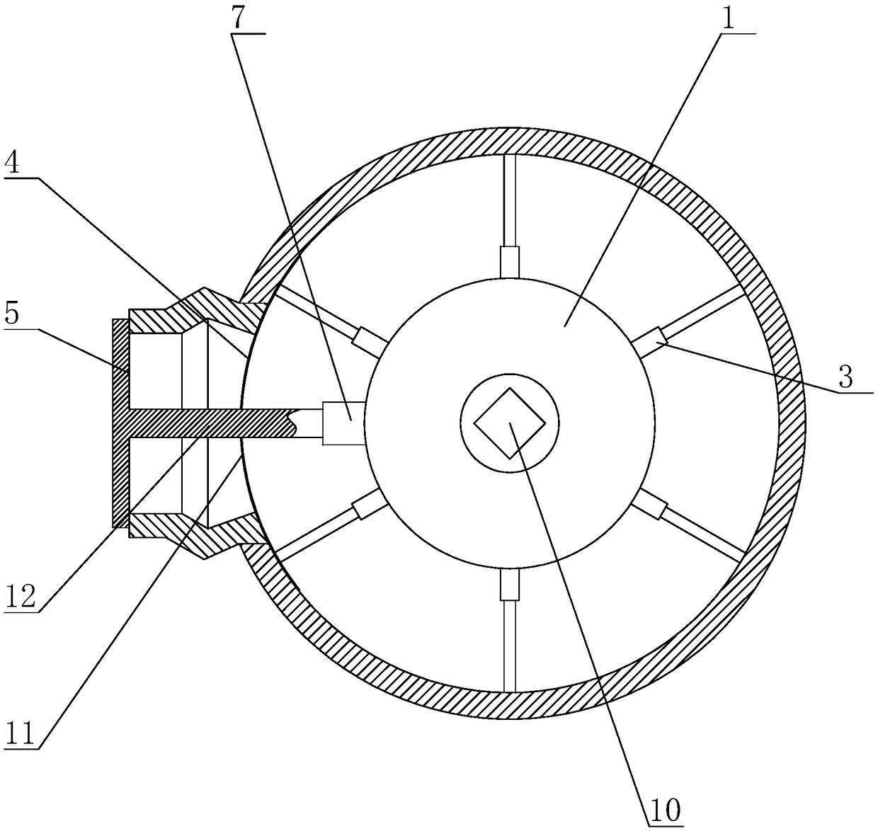
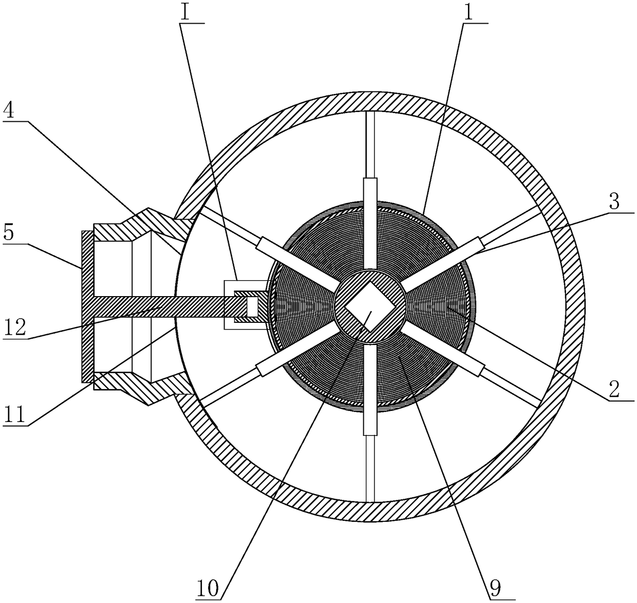
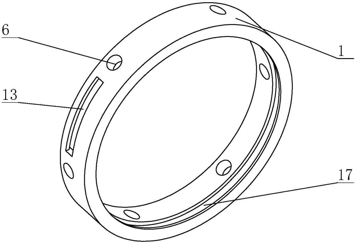
[0029] The present invention is a nuclear power pipeline branch nozzle welding mold. The main structure includes an outer ring 1, an inner disk 2, a brace 3, an arc-shaped backing plate 4, and a pressure plate 5. The outer ring 1 is provided with a plurality of through holes 6, so The outer surface of the outer ring 1 is provided with a sliding groove 13 with a T-shaped cross section, a fixed post 7 is slidably connected to the sliding groove 13 and a threaded hole is provided on the fixed post 7, and the inner disk 2 is arranged on the outer ring 1, the inner surface of the outer ring 1 is provided with a groove 14, the inner disk 2 is arranged in the groove 14 and rotates along the groove 14, a plane thread structure 9 is provided on one side of the inner disk 2, and the inner disk 2. A rocker socket 10 is provided at the center position; the strut 3 is a telescopic rod with an adjustable length, and a plurality of the struts 3 are distributed along the circular array of the i...


PUM


Abstract

The invention discloses a nuclear power pipeline branch pipe opening welding mould and mainly relates to the field of welding moulds. The welding mould comprises an outer ring, an inner disc, supporting rods, an arc-shaped base plate and a pressing plate. The outer ring is provided with multiple through holes. A fixing column is arranged on the outer surface of the outer ring. A locating hole is formed in the fixing column. The inner disc is arranged in the outer ring. One side face of the inner disc is provided with a plane thread structure. The ends of the multiple supporting rods penetratethrough the through holes and are installed on plane threads correspondingly and connected with a plane thread structure in a transmission manner. The arc-shaped base plate is provided with a via hole. The diameter of the pressing plate is larger than the hole diameter of branch pipe openings. The pressing plate is provided with a fixing rod. The tail end of the fixing rod penetrates through the via hole and is fixed to the locating hole, and the pressing plate presses the ends faces of the branch pipe openings. The welding mould has the beneficial effects that under the circumstance of not adjusting rotating of nuclear power pipelines, two branch pipe openings can be welded, the preparation work load before whole welding is small, the difficulty is low, and the welding efficiency is improved greatly.

Description

Technical field [0001] The invention relates to the field of welding molds, in particular to a welding mold for branch nozzles of nuclear power pipelines. Background technique [0002] As attached in the description Figure 5 As shown, there are two branch nozzles on the nuclear power main pipeline, the first branch nozzle is on the side of the nuclear power main pipeline, and the second branch nozzle is on the oblique side upward of the nuclear power main pipeline. The welding work of these two branch pipes is extremely demanding. The existing method is to weld each branch pipe one by one, with the nozzle welding hole on the nuclear power main pipeline facing upwards, and then install a supporting device inside the nuclear power main pipeline , The branch pipe to be welded is supported from the inside of the nuclear power main pipeline, and then the welding work is carried out. When the second branch pipe is welded, the rotating nuclear power main pipeline has to be re-adjusted ...

Claims


Application Information

Patent Timeline
Patent Type & Authority Applications(China)
IPC IPC(8): B23K37/053
CPCB23K37/0531
Inventor 刘兆云
Owner 朱兴兴
Learn More