Roof plate with high capacity of resisting pulling force of wind
A technology of roof panels and floor panels, applied in the field of roof panels, can solve problems such as unsuitable use and poor wind resistance, and achieve the effects of saving materials, reducing horizontal lap joints, and reducing the chance of water seepage
- Summary
- Abstract
- Description
- Claims
- Application Information
AI Technical Summary
Problems solved by technology
Method used
Image
Examples
Embodiment 1
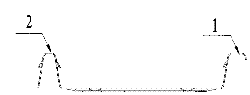
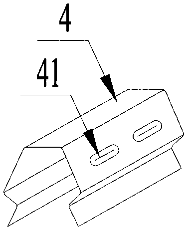
[0021] Such as Figure 3-5 As shown, a roof panel with good wind resistance includes a male rib 1, a female rib 2 and a base plate 5, and the male rib 1 and the female rib 2 are arranged on the base plate 5, and also includes an anti-snap cap 4, and the male rib 1 It is buckled together with the female rib 2 and fixed by the buckle-resistant cap 4. The male rib 1 and the female rib 2 are provided with a buckling point 3. The cross-section of the buckle-resistant cap 4 is similar to that of the buckled male rib 1 and the female rib 2 , and can just be stuck on the male rib 1 and the female rib 2 . Four grooves 41 are provided on the outside of the anti-snapping cap 4, and four protrusions are provided on the opposite inner side thereof, and can slide on the male rib 1 and the female rib 2 through the four protrusions. The length of the male rib 1 and the female rib 2 is 1000 mm, the length of the bottom plate 5 is 750 mm, and the buckling point 3 is 5.2 mm.
[0022] The effec...
Embodiment 2
[0024] A roof panel with good wind resistance, including a male rib, a female rib and a base plate, the male rib and the female rib are arranged on the base plate, and also includes an anti-snap cap, the male rib and the female rib are buckled together, and the The buckle cap is fixed, and there are buckle points on the male and female ribs. The cross-section of the buckle-resistant cap is similar to the cross-section of the buckled male rib and the female rib, and can just be stuck on the male rib and the female rib. Four grooves are arranged on the outside of the buckle-resistant cap, and four protrusions are arranged on the opposite inner side thereof, and can slide on the male rib and the female rib through the four protrusions. The length of the male and female ribs is 700mm, the length of the bottom plate is 450mm, and the buckle point is 3mm.
Embodiment 3
[0026] A roof panel with good wind resistance, including a male rib, a female rib and a base plate, the male rib and the female rib are arranged on the base plate, and also includes an anti-snap cap, the male rib and the female rib are buckled together, and the The buckle cap is fixed, and there are buckle points on the male and female ribs. The cross-section of the buckle-resistant cap is similar to the cross-section of the buckled male rib and the female rib, and can just be stuck on the male rib and the female rib. Four grooves are arranged on the outside of the buckle-resistant cap, and four protrusions are arranged on the opposite inner side thereof, and can slide on the male rib and the female rib through the four protrusions. The length of the male and female ribs is 2000mm, the length of the bottom plate is 1500mm, and the buckle point is 8mm.
PUM
 Abstract
Description
Claims
Application Information
 - R&D Engineer
- R&D Manager
- IP Professional
- Industry Leading Data Capabilities
- Powerful AI technology
- Patent DNA Extraction
Browse by: Latest US Patents, China's latest patents, Technical Efficacy Thesaurus, Application Domain, Technology Topic, Popular Technical Reports.
© 2024 PatSnap. All rights reserved.Legal|Privacy policy|Modern Slavery Act Transparency Statement|Sitemap|About US| Contact US: help@patsnap.com


