Waste gas treatment equipment for reducing harmful ingredients of discharged tail gas

A technology for waste gas treatment equipment and harmful components, which is applied in the field of waste gas treatment equipment for reducing harmful components of exhaust gas, can solve problems such as difficulty in opening and closing, single structural design of inspection doors, and difficulty in reflecting humanized design, etc., so as to reduce harmful components and structure Simple, easy-to-use effects

Pending Publication Date: 2018-11-30
湖州山海环保工程有限公司
View PDF0 Cites 0 Cited by
  • Summary
  • Abstract
  • Description
  • Claims
  • Application Information

AI Technical Summary

Problems solved by technology

[0002] Exhaust gas treatment equipment mainly refers to a kind of environmental protection equipment that protects the environment and purifies the air by recycling or removing or reducing harmful components of exhaust gas by using different technologies; the existing exhaust gas treatment equipment has certain disadvantages in use. The structural design of the inspection door is single, it is difficult to open and close quickly and conveniently, which brings no change to the use, and the design without handle requires the hand to hold the gas collecting cover to adjust the orientation, which is difficult to reflect the humanized design. brought a certain impact, for this reason, we propose a waste gas treatment equipment that reduces the harmful components of the tail gas

Method used


Image

  • Waste gas treatment equipment for reducing harmful ingredients of discharged tail gas
  • Waste gas treatment equipment for reducing harmful ingredients of discharged tail gas
  • Waste gas treatment equipment for reducing harmful ingredients of discharged tail gas

Examples


Embodiment Construction

[0016] In order to make the technical means, creative features, goals and effects achieved by the present invention easy to understand, the present invention will be further described below in conjunction with specific embodiments.

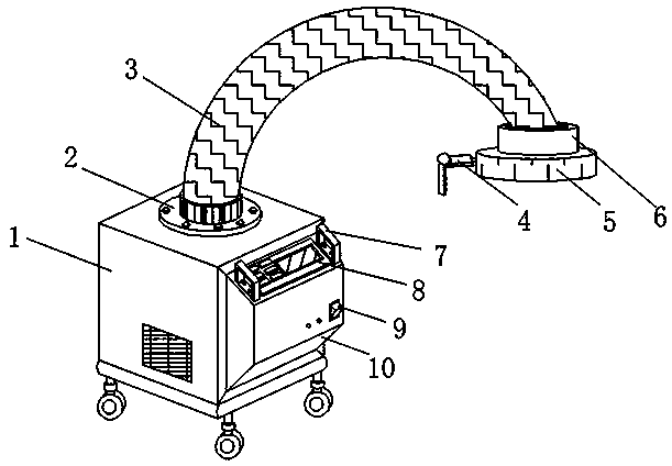
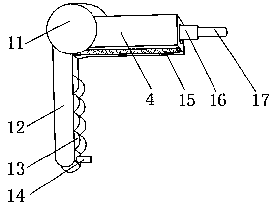
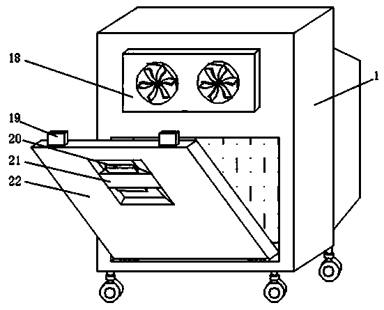
[0017] Such as Figure 1-3 As shown in the figure, an exhaust gas treatment device for reducing harmful components in exhaust gas includes a housing 1, an electric control cabinet 10 is arranged in the middle of the front end of the housing 1, and the front end of the electric control cabinet 10 is arranged near the edge of the bottom end There are switch buttons 9, an operation panel 8 is arranged at the middle position of the upper end surface of the electric control box 10, and handles 7 are fixedly installed on both sides of the upper end surface of the electric control box 10 close to the operation panel 8, and the middle position of the upper end of the housing 1 is A universal suction pipe 3 is provided at the joint, and a connecting flange...


PUM


Abstract

The invention discloses waste gas treatment equipment for reducing harmful ingredients of discharged tail gas. The waste gas treatment equipment comprises a casing, wherein an electric control machinebox is arranged in the middle position of the front end surface of the casing; a switch press key is arranged in a position near the bottom end edge of the front end surface of the electric control machine box; an operation panel is arranged in the middle position of the upper end surface of the electric control box; pull handles are fixedly arranged in positions, near the two sides of the operation panel, of the upper end surface of the electric control machine box; a universal gas suction pipe is arranged in the middle position of the upper end of the casing; a connecting flange is arrangedin the connecting position of the universal gas suction pipe and the casing; the universal gas suction pipe is fixedly connected with the casing through the connecting flange; one end of the universal gas suction pipe is provided with an integration cover. The waste gas treatment equipment for reducing harmful ingredients of discharged tail gas has the advantages that a spring clamp buckle and the folding type handles are installed; convenience is brought to the use; the position regulation of the air suction pipe is convenient; the humanized design is shown; better use prospects are brought.

Description

technical field [0001] The invention relates to the field of exhaust gas treatment equipment, in particular to an exhaust gas treatment equipment for reducing harmful components of tail gas. Background technique [0002] Exhaust gas treatment equipment mainly refers to a kind of environmental protection equipment that protects the environment and purifies the air by recycling or removing or reducing harmful components of exhaust gas by using different technologies; the existing exhaust gas treatment equipment has certain disadvantages in use. The structural design of the inspection door is single, it is difficult to open and close quickly and conveniently, which brings no change to the use, and the design without handle requires the hand to hold the gas collecting cover to adjust the orientation, which is difficult to reflect the humanized design. Therefore, we propose a waste gas treatment equipment that reduces the harmful components of the tail gas. Contents of the inve...

Claims


Application Information

Patent Timeline
Patent Type & Authority Applications(China)
IPC IPC(8): B01D46/00
CPCB01D46/0045B01D46/62
Inventor 胡航海
Owner 湖州山海环保工程有限公司
Why Eureka
Try Eureka