A hoop device and method for preventing misoperation of a brake knife
An anti-misoperation and knife technology, applied in electrical components and other directions, can solve the problems of unsuitable knife and high cost, and achieve the effects of low cost, low manufacturing cost and convenient transformation.
- Summary
- Abstract
- Description
- Claims
- Application Information
AI Technical Summary
Problems solved by technology
Method used
Image

Examples
Embodiment 1
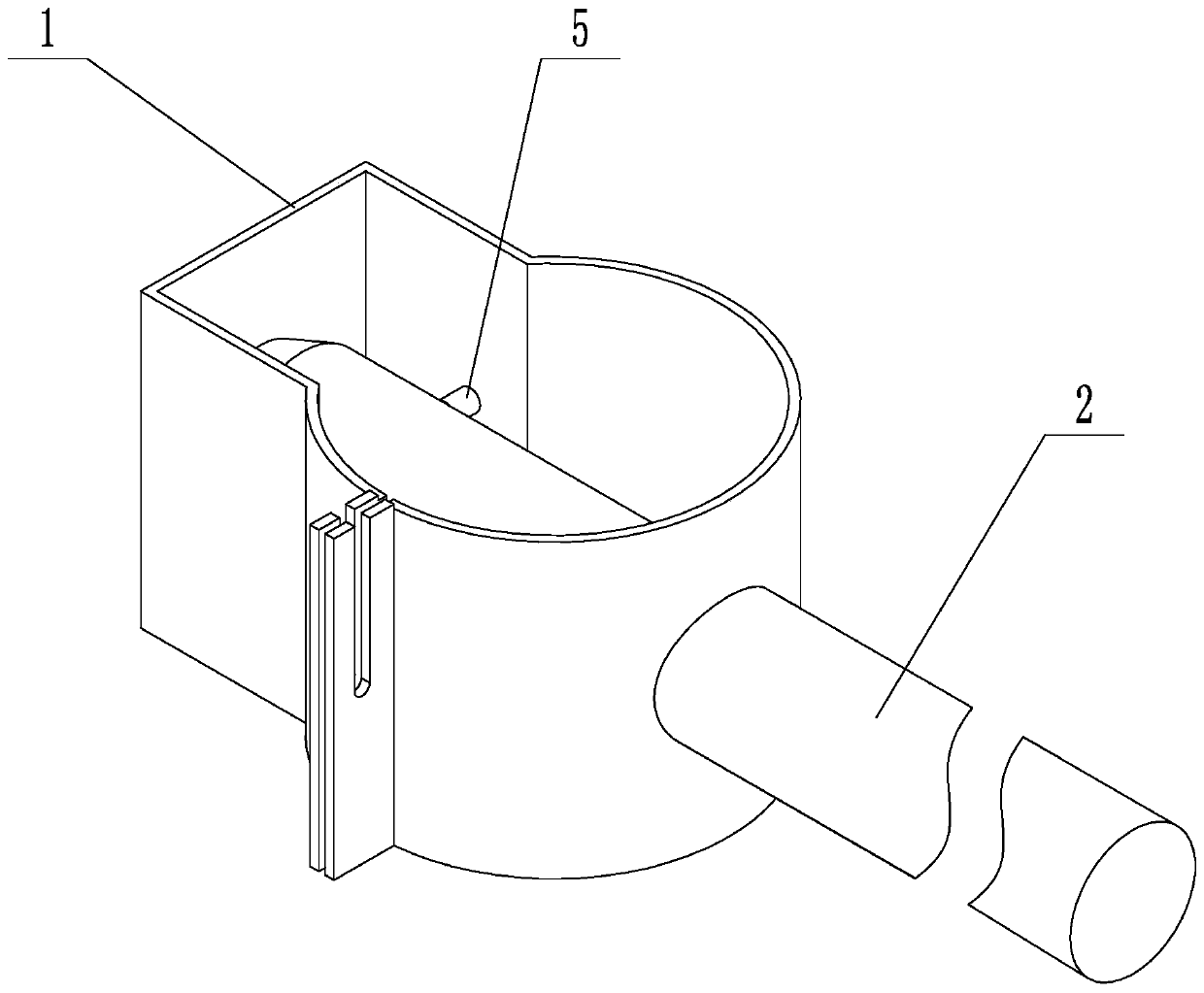
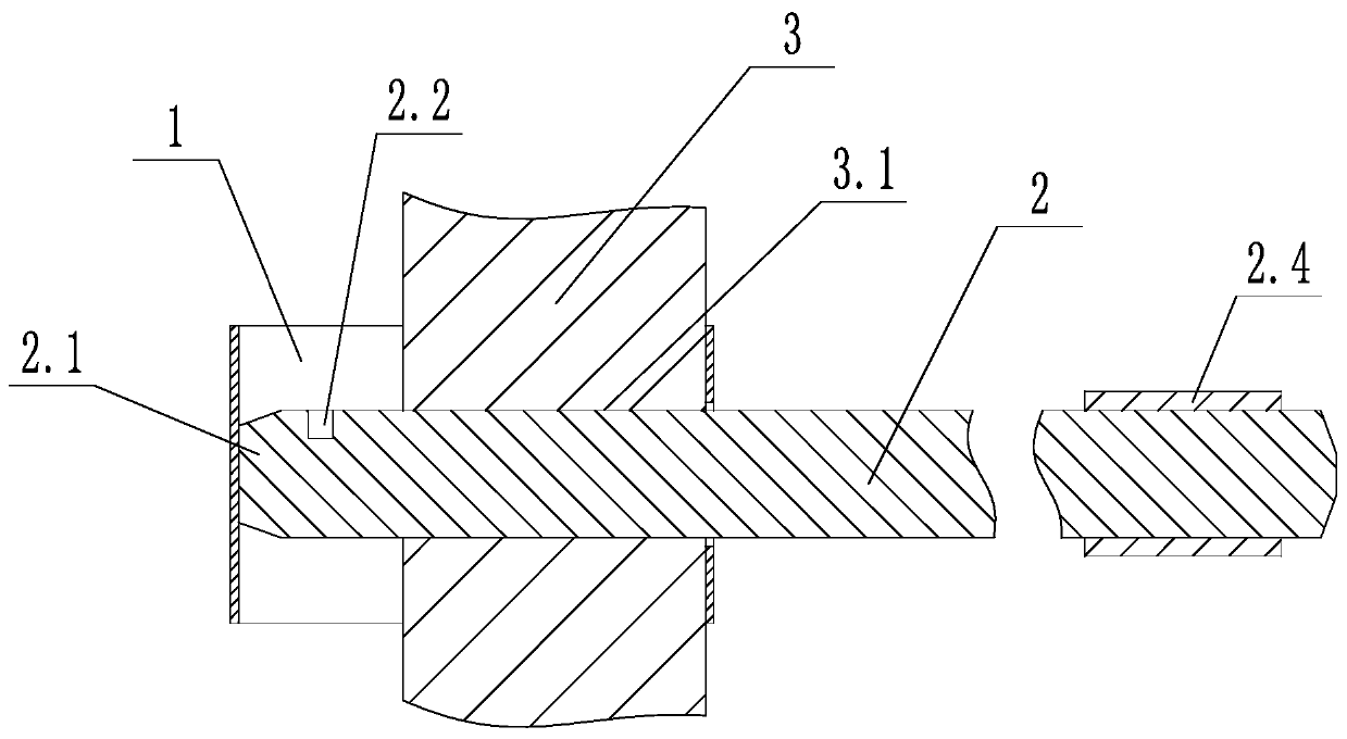
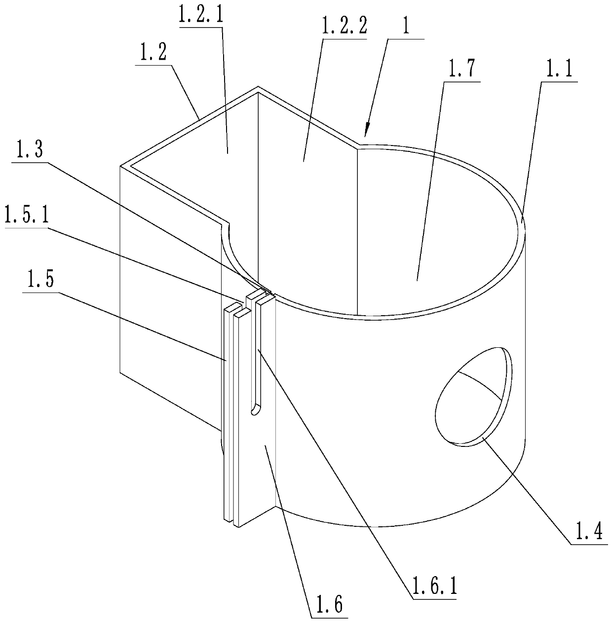
[0033] Such as Figure 1 to Figure 3 As shown in the figure, a hoop device for preventing misoperation of the brake knife includes a hoop body 1 and an operating rod 2. The diameter of the operating rod 2 is adapted to the diameter of the operating hole 3.1 on the knife transmission shaft 3. The hoop body 1 It includes a cylindrical hoop 1.1, a square hoop 1.2, an elastic opening 1.3, an operation opening 1.4, a first fastening piece 1.5, and a second fastening piece 1.6. The square hoop 1.2 is fixed and connected with the cylindrical hoop 1.1. Enclosing a fixed cavity 1.7, the two ends of the fixed cavity 1.7 communicate with the outside world; the operation opening 1.4 is arranged on the position opposite to the outer wall of the cylindrical hoop 1.1 and the square hoop 1.2, and the diameter of the operation opening 1.4 is larger than the operation The diameter of the hole 3.1; the elastic opening 1.3 is arranged between the square hoop body 1.2 and the operation opening 1.4...
Embodiment 2
[0036] Such as Figure 4 and Figure 5 As shown, on the basis of Embodiment 1, the square hoop body 1.2 includes a first side wall 1.2.1 and two second side walls 1.2.2, and the two second side walls 1.2.2 are respectively connected to the first side The wall 1.2.1 is connected, the second side wall is connected with the cylindrical hoop body 1.1, the first side wall 1.2.1 is opposite to the operation opening 1.4, and the inner wall of the second side wall is provided with an elastic buckle 5, and the elastic protrusion The buckle 5 includes a base 5.1, a compression spring 5.2 and a telescoping head 5.3, the base 5.1 is fixed to the first side wall 1.2.1, the telescoping head 5.3 is slidingly connected to the base 5.1, one end of the compression spring 5.2 is in contact with the base 5.1, and the other end of the compression spring 5.2 Contact with telescoping head 5.3.
[0037] The side wall of the operating rod 2 is provided with a card hole 2.2, a chute 2.3 and an elasti...
Embodiment 3
[0040] On the basis of Example 2, a rubber sheet 1.8 is provided on the inner wall of the cylindrical hoop 1.1. The first fastening sheet 1.5 is provided with a first strip-shaped hole 1.5.1, and one side of the first strip-shaped hole 1.5.1 communicates with the outside world; the second fastening sheet 1.6 is provided with a second strip shaped hole 1.6.1, one side of the second strip-shaped hole 1.6.1 communicates with the outside world, the first strip-shaped hole 1.5.1 and the second strip-shaped hole 1.6.1 are set at opposite positions, and the fixing bolt 4 passes through the second strip-shaped hole 1.6.1 A strip of holes 1.5.1 and a second strip of holes 1.6.1. The strip-shaped hole can ensure that the fixing bolt 4 can still be installed within a certain installation error. At the same time, it is convenient to fix and take out the bolts.
PUM
 Abstract
Description
Claims
Application Information
 - R&D
- Intellectual Property
- Life Sciences
- Materials
- Tech Scout
- Unparalleled Data Quality
- Higher Quality Content
- 60% Fewer Hallucinations
Browse by: Latest US Patents, China's latest patents, Technical Efficacy Thesaurus, Application Domain, Technology Topic, Popular Technical Reports.
© 2025 PatSnap. All rights reserved.Legal|Privacy policy|Modern Slavery Act Transparency Statement|Sitemap|About US| Contact US: help@patsnap.com