
Push rod clamping type rope towing system and working method thereof

A rope and push rod technology, which is applied to the field of push rod clamping type rope towing systems, can solve the problem that the float ball, the rope rope or the seedling rope cannot be smoothly hooked, the operation efficiency is not significantly improved, and the float ball is easily crushed. and other problems, to achieve the effect of ingenious action design, improved work efficiency, and convenient operation.

Active Publication Date: 2018-11-30
FISHERY MACHINERY & INSTR RES INST CHINESE ACADEMY OF FISHERY SCI
View PDF13 Cites 4 Cited by
  • Summary
  • Abstract
  • Description
  • Claims
  • Application Information

AI Technical Summary

Problems solved by technology

[0002] At present, kelp harvesting ships mostly use a conveying system consisting of a motor, a conveyor belt / chain, and claws or hooks installed on the conveyor belt / chain to pick up the floating ball, rope, or seedling rope on the rope of cultured kelp. kelp, and tow the ship forward, such as the Chinese patent applications for patents with application numbers 201310399215.0, 201610838975.0, 201520194379.4, 201611090308.5, 201420627155.3, 201420666807.4. There are following problems: 1) in harvesting When kelp is used, it will fluctuate significantly up and down with the tide and wind and waves, and the up and down movement of the rope can reach 1.5-2m, which makes the claws or hooks installed on the conveyor belt / chain unable to smoothly hook the floating ball or rope Or seedling rope, resulting in no significant improvement in operating efficiency, and it is very easy to form a situation where kelp is missed; 2) The claws are easy to crush the floating ball, resulting in loss of supplies

Method used


Image

  • Push rod clamping type rope towing system and working method thereof
  • Push rod clamping type rope towing system and working method thereof
  • Push rod clamping type rope towing system and working method thereof

Examples


Embodiment Construction

[0027] The present invention will be further described below in conjunction with the accompanying drawings and specific embodiments.

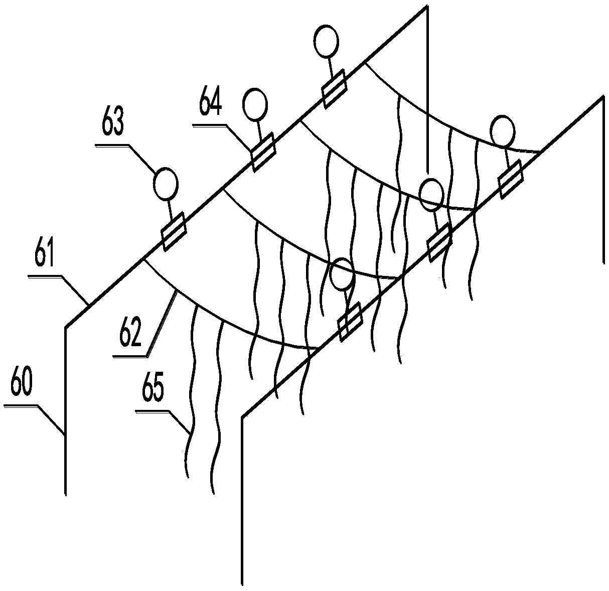
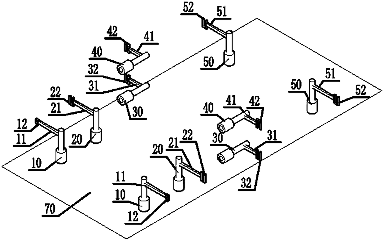
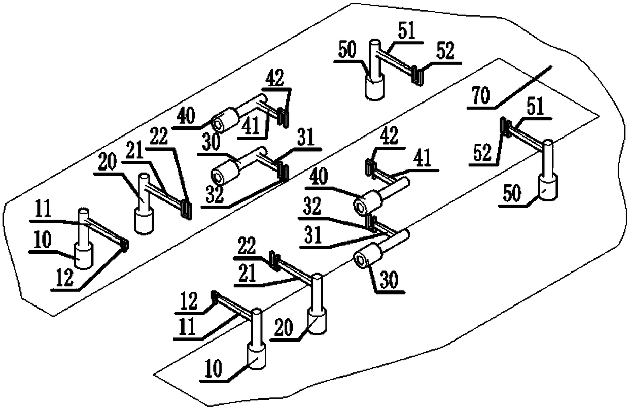
[0028] see Figure 1-6 , the push rod clamping type rope towing system, including an electro-hydraulic push rod 10 extending and contracting in the vertical direction, an electro-hydraulic push rod 20 extending and contracting in the vertical direction, and an electro-hydraulic push rod 30 extending and contracting in the ship's length direction arranged in sequence; Placed directly above the electrohydraulic pushrod 30, the electrohydraulic pushrod 40 stretches along the length of the ship; the electrohydraulic pushrod 50 stretches vertically; the support arm 11 connecting the electrohydraulic pushrod 10 and the guide limit frame 12; Connect the support arm 21 of the electrohydraulic push rod 20 and the clamp 22; connect the support arm 31 of the electrohydraulic push rod 30 and the clamp 32; connect the support arm 41 of the electrohydraulic ...


PUM


Abstract

The invention relates to a push rod clamping type rope towing system. An electro-hydraulic push rods I, an electro-hydraulic push rod II and an electro-hydraulic push rod V which are vertically telescopic are arranged in series along the inner side or outer side of the ship; an electro-hydraulic push rod III and an electro-hydraulic push rod IV are arranged at a position between the electro-hydraulic push rod II and the electro-hydraulic push rod V; each electro-hydraulic push rod extends support arm outwardly; a first support arm is provided with a guiding limit frame at the end part; a second support arm, a third support arm and a fifth support arm are provided with clamps with openings facing upward, and the fourth support arm end is provided with a clamp with an opening facing downward; the guide limit frame is provided with a shift lever that divides the limit frame into two, and one end of the shift lever and the limit frame are hinged by an elastic reset hinge. The invention solves the problems that the claw or the hook mounted on the conveyor belt / chain cannot smoothly take off the floating ball or the ropes, the seedling ropes, and the floating balls are damaged due to theforce.

Description

technical field [0001] The invention relates to a kelp rope towing system, in particular to a push rod clamping type rope towing system and a working method thereof. Background technique [0002] At present, kelp harvesting ships mostly use a conveying system consisting of a motor, a conveyor belt / chain, and claws or hooks installed on the conveyor belt / chain to pick up the floating ball, rope, or seedling rope on the rope of cultured kelp. Kelp, and tow the ship to advance, as the application number is 201310399215.0, 201610838975.0, 201520194379.4, 201611090308.5, 201420627155.3, 201420666807.4 Patent Chinese patent application, although adopting the above-mentioned transmission method has the characteristics of continuous work, but also has the following problems in harvesting: When kelp is used, it will fluctuate significantly up and down with the tide and wind and waves, and the up and down movement of the rope can reach 1.5-2m, which makes the claws or hooks installed ...

Claims


Application Information

Patent Timeline
IPC IPC(8): A01D44/00
CPCA01D44/00Y02A40/80
Inventor 刘和炜
Owner FISHERY MACHINERY & INSTR RES INST CHINESE ACADEMY OF FISHERY SCI
Learn More