Crop straw roll cutting operation mechanism
A technology for crop straw and operating mechanism, which is applied in agricultural machinery and implements, agriculture, cutters, etc., can solve the problem of difficulty in ensuring that the crop straw is completely cut off, and achieve the effects of reducing equipment costs and improving quality and reliability.
- Summary
- Abstract
- Description
- Claims
- Application Information
AI Technical Summary
Problems solved by technology
Method used
Image
Examples
Embodiment 1
[0038] A crop straw rolling cutting operation mechanism, including a frame 1, a conveying mechanism 2 and a rolling cutting mechanism body 3 installed on the frame 1;
[0039] The conveying mechanism 2 is located in front of the rolling cutting mechanism body 3 relative to the forward direction of the frame 1, and the conveying mechanism 2 is used to transport crop straw to the rolling cutting mechanism body 3;
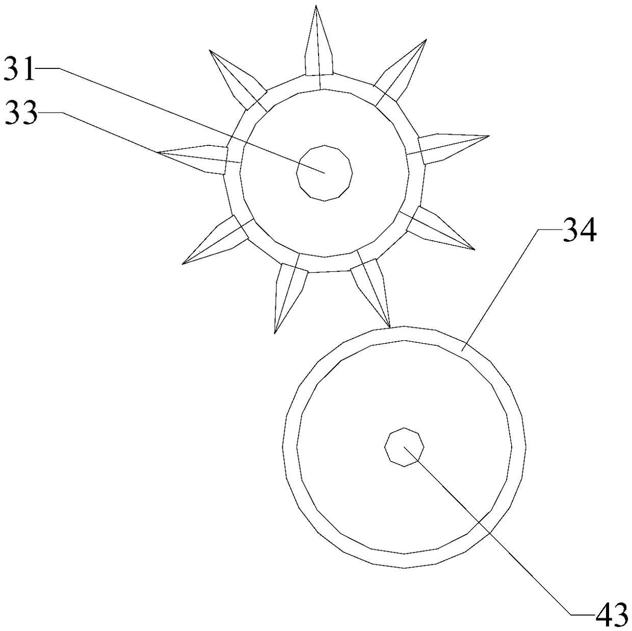
[0040] The roll cutting mechanism body 3 includes a first stalk cutting rotor 31 and a second stalk cutting rotor 32, the rotation of the first stalk cutting rotor 31 is opposite to that of the second stalk cutting rotor 32, and the rotation direction of the first stalk cutting rotor 31 is More than three cutting knives 33 are arranged at intervals on the circumference, and a stalk cutting pier 34 made of elastic material is provided on the circumferential surface of the second stalk cutting rotor 32 .
[0041] The conveying mechanism 2 includes a pair of guiding serv...
Embodiment 2
[0047] A crop straw rolling cutting operation mechanism, including a frame 1, a conveying mechanism 2 and a rolling cutting mechanism body 3 installed on the frame 1;
[0048] The conveying mechanism 2 is located in front of the rolling cutting mechanism body 3 relative to the forward direction of the frame 1, and the conveying mechanism 2 is used to transport crop straw to the rolling cutting mechanism body 3;
[0049] The roll cutting mechanism body 3 includes a first stalk cutting rotor 31 and a second stalk cutting rotor 32, the rotation of the first stalk cutting rotor 31 is opposite to that of the second stalk cutting rotor 32, and the rotation direction of the first stalk cutting rotor 31 is More than three cutting knives 33 are arranged at intervals on the circumference, and a stalk cutting pier 34 made of elastic material is provided on the circumferential surface of the second stalk cutting rotor 32 .
[0050] The conveying mechanism 2 includes a pair of guiding serv...
Embodiment 3
[0058] A crop straw rolling cutting operation mechanism, including a frame 1, a conveying mechanism 2 and a rolling cutting mechanism body 3 installed on the frame 1;
[0059] The conveying mechanism 2 is located in front of the rolling cutting mechanism body 3 relative to the forward direction of the frame 1, and the conveying mechanism 2 is used to transport crop straw to the rolling cutting mechanism body 3;
[0060] The roll cutting mechanism body 3 includes a first stalk cutting rotor 31 and a second stalk cutting rotor 32, the rotation of the first stalk cutting rotor 31 is opposite to that of the second stalk cutting rotor 32, and the rotation direction of the first stalk cutting rotor 31 is More than three cutting knives 33 are arranged at intervals on the circumference, and a stalk cutting pier 34 made of elastic material is provided on the circumferential surface of the second stalk cutting rotor 32 .
[0061] The conveying mechanism 2 includes a pair of guiding serv...
PUM
 Abstract
Description
Claims
Application Information
 - Generate Ideas
- Intellectual Property
- Life Sciences
- Materials
- Tech Scout
- Unparalleled Data Quality
- Higher Quality Content
- 60% Fewer Hallucinations
Browse by: Latest US Patents, China's latest patents, Technical Efficacy Thesaurus, Application Domain, Technology Topic, Popular Technical Reports.
© 2025 PatSnap. All rights reserved.Legal|Privacy policy|Modern Slavery Act Transparency Statement|Sitemap|About US| Contact US: help@patsnap.com


