
Secondary side multi-winding spliced type energy-saving transformer used in distribution network

An energy-saving transformer and multi-winding technology, applied in the field of transformers, can solve the problems of long economic transmission distance, moisture at the bottom of the transformer, transformer leakage, etc., to save energy loss, reduce the risk of leakage, and reduce no-load energy loss. Effect

Inactive Publication Date: 2018-11-27
ANHUI HUAZHENG ELECTRIC
View PDF8 Cites 1 Cited by
  • Summary
  • Abstract
  • Description
  • Claims
  • Application Information

AI Technical Summary

Problems solved by technology

[0002] Transformers can convert electrical energy into high voltage and low current form, and then convert back, thus greatly reducing the loss of electrical energy in the transmission process, making the economic transmission distance of electrical energy longer, so that power plants can be built in Far away from the place where electricity is used, most of the world's electricity finally reaches the user after a series of transformations; at present, when many transformers are in use, there will be some gaps in the manufacturing process, resulting in the transformer being in use. Large no-load loss, and because the heat is volatilized upward, it is easy to cause the bottom of the transformer box to be damp in rainy and snowy weather, which in turn leads to leakage of the transformer

Method used


Image

  • Secondary side multi-winding spliced type energy-saving transformer used in distribution network
  • Secondary side multi-winding spliced type energy-saving transformer used in distribution network

Examples


Embodiment Construction

[0021] The following will clearly and completely describe the technical solutions in the embodiments of the present invention with reference to the accompanying drawings in the embodiments of the present invention. Obviously, the described embodiments are only some, not all, embodiments of the present invention. All other embodiments obtained by persons of ordinary skill in the art based on the embodiments of the present invention belong to the protection scope of the present invention.

[0022] According to an embodiment of the present invention, an energy-saving secondary-side multi-winding parallel connection type energy-saving transformer used in a distribution network is provided.

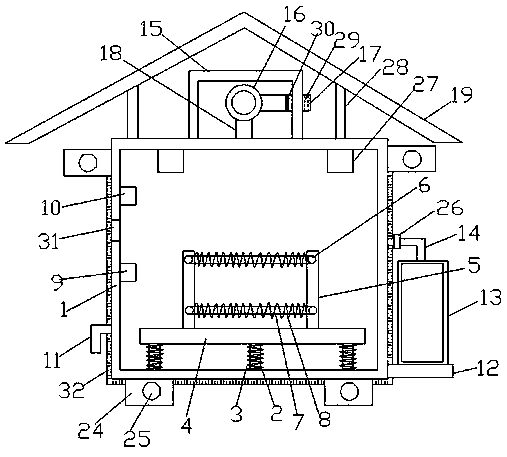
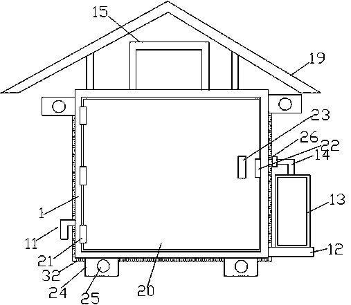
[0023] Such as Figure 1-2 As shown, according to an embodiment of the present invention, a secondary multi-winding parallel-connected energy-saving transformer used in a distribution network includes a transformer box 1, and a plurality of telescopic rods 2 are arranged at the inner bottom of...


PUM


Abstract

The invention discloses a secondary side multi-winding spliced type energy-saving transformer used in a distribution network. The secondary side multi-winding spliced type energy-saving transformer used in the distribution network comprises a transformer tank, wherein a plurality of telescopic rods are arranged at the bottom end of the inside of the transformer tank; a spring is arranged on the outside of each telescopic rod; a connecting plate is arranged at the top end of each telescopic rod; yokes are separately arranged on two sides of the top end of the connecting plate; magnetizers are separately arranged at the bottom end and the top end of each yoke; the magnetizers on the same horizontal line are connected through a transformer core; a coil is arranged on the outside of each transformer core; a high-voltage binding post is arranged in the middle of a side wall of the inside of the transformer tank; a low-voltage binding post is arranged on the top of the high-voltage binding post; a waterproof layer is arranged on the outside of the transformer tank; an exhaust opening is formed in the bottom end of one side of the transformer tank; a supporting plate is arranged on the side, which is away from the exhaust opening, of the bottom end of one side of the transformer tank; a dry powder extinguisher is arranged at the top end of the supporting plate; a spraying tube is arranged in the middle of the top end of the dry powder extinguisher; the side, which is away from the dry powder extinguisher, of the spraying tube is connected with the transformer tank; and a protective cover is arranged in the middle of the top end of the transformer tank.

Description

technical field [0001] The invention relates to the technical field of transformers, in particular to an energy-saving secondary-side multi-winding parallel-connected energy-saving transformer used in a distribution network. Background technique [0002] Transformers can convert electrical energy into high voltage and low current form, and then convert back, thus greatly reducing the loss of electrical energy in the transmission process, making the economical transmission distance of electrical energy longer, so that power plants can be built in Far away from the place where electricity is used, most of the world's electricity finally reaches the user after a series of transformations; at present, when many transformers are in use, there will be some gaps in the manufacturing process, which will cause the transformer to be used. Large no-load loss, and because the heat is volatilized upward, it is easy to cause the bottom of the transformer box to be damp in rainy and snow...

Claims


Application Information

Patent Timeline
Patent Type & Authority Applications(China)
IPC IPC(8): H01F27/02H01F27/06A62C3/16A62C31/00
CPCA62C3/16A62C31/00H01F27/02H01F27/06
Inventor 李文奇邹永辉
Owner ANHUI HUAZHENG ELECTRIC
Learn More