
Metering control method of rotor scale feeding device

A technology of a feeding device and a control method, which is applied in the field of control, and can solve problems such as material centroid deviation, increased material quantity difference, material centroid deviation, and increased consumption, so as to improve production efficiency and product quality, and increase the speed of adjustment and precision, reducing the effect of uneven material

Inactive Publication Date: 2018-11-27
YANSHAN UNIV
View PDF7 Cites 5 Cited by
  • Summary
  • Abstract
  • Description
  • Claims
  • Application Information

AI Technical Summary

Problems solved by technology

[0002] Due to the mechanical characteristics of the rotor scale feeding device, it is impossible to evenly distribute the materials in the fan-shaped space between the blades of the rotary wheel of the rotor scale feeding device, which makes the difference in the amount of material in each fan-shaped space very large, and The number of blades of the rotary wheel should not be too many, which will occupy a limited space, increase the overall weight, and increase consumption, which will cause a large deviation in the centroid of the material
The electrical control system needs to adjust the speed of the rotary wheel of the equipment, which will further increase the difference in the amount of materials in each fan-shaped space and the deviation of the centroid of the materials, and the continuous measurement control method is to effectively weigh the materials in the section Calculated according to the uniform distribution, the centroid position of the material remains unchanged, which will have a great impact on the accuracy of the given material, and cannot guarantee the stability of the instantaneous feeding rate, causing a large amount of economic losses in actual production, even for Many production process requirements cannot be met

Method used


Image

  • Metering control method of rotor scale feeding device
  • Metering control method of rotor scale feeding device
  • Metering control method of rotor scale feeding device

Examples


Embodiment Construction

[0028] specific implementation plan

[0029] The technical solutions of the present invention will be further described below in conjunction with the accompanying drawings and through specific implementation methods.

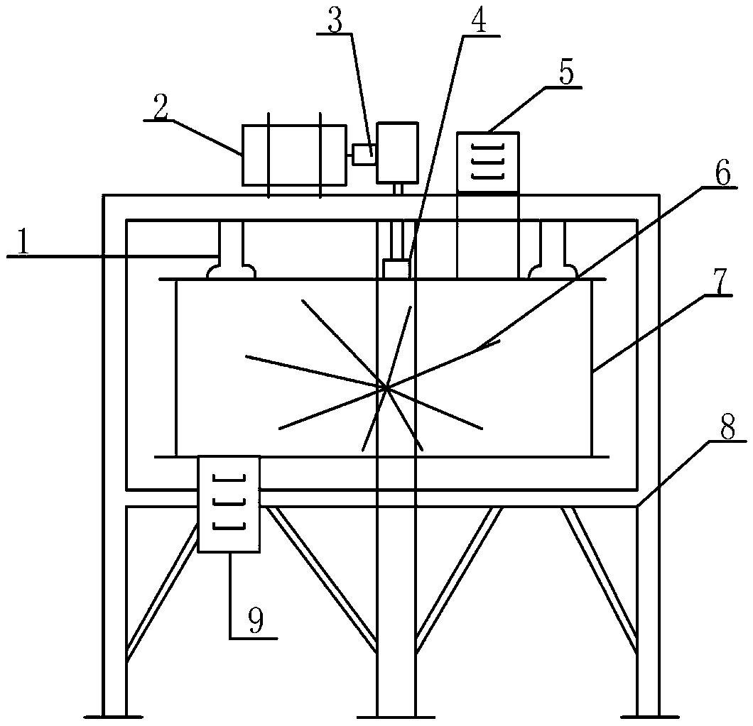
[0030] The present invention is an embodiment of a metering control method of a rotor scale feeding device, such as figure 1 As shown, a rotor scale feeding device for reference in this embodiment includes two hoisting bearings 1, a motor 2, a speed measuring device 3, a weighing device 4, a feed port 5, a rotary wheel 6, a scale body 7, Frame 8 and outlet 9.

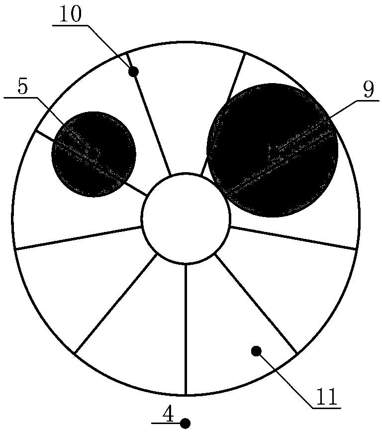
[0031] The line connecting the two fulcrums of the two hoisting bearings 1 in the above device should coincide with the line connecting the centers of the feed inlet 5 and the outlet 9, and the two fulcrums are distributed symmetrically and equidistantly; The other side and on the centerline of the line connecting the fulcrums of the two hoisting bearings 1; there should be a feed port baffle on the fee...


PUM


Abstract

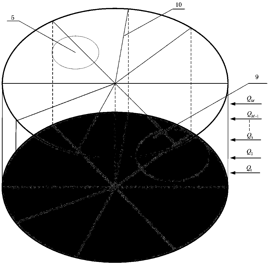
The invention discloses a metering control method of a rotor scale feeding device. The method comprises the following steps of dividing the flow setting values into a plurality of grades from low to high according to different scale types and different scale coefficients, setting different values for material amount in the effective weighing range of the rotary wheel of the scale according to different grades of the flow setting values, obtaining the corresponding rotary wheel speed set value according to the flow setting values and the corresponding material amount setting values, and then equally dividing the effective weighing space of the rotary wheel into N virtual fan-shaped spaces, weighing and calculating the materials in each virtual fan-shaped space, and adjusting the opening degree of the feeding hole baffle and the speed of the rotary wheel according to the material amount in each virtual fan-shaped space, and performing real-time monitoring on the material flow. By controlling the speed of the rotary wheel and the opening degree of the material port baffle, the precision and accuracy of material metering can be effectively improved.

Description

technical field [0001] The invention relates to the technical field of control methods, in particular to a metering control method for a rotor scale feeding device. The metering control method of the rotor scale feeding device on the market adopts the continuous metering control method: the effective fan-shaped weighing section weighs the weight of the real-time material, and the product of the weight and the real-time speed is the real-time flow rate, and then according to the design of production needs The flow rate is adjusted by electrical control to adjust the real-time speed of the rotary wheel of the equipment, so that the real-time flow rate delivered is equal to the design flow rate, and the purpose of quantitative delivery is achieved. technical background [0002] Due to the mechanical characteristics of the rotor scale feeding device, it is impossible to evenly distribute the materials in the fan-shaped space between the blades of the rotary wheel of the rotor sc...

Claims


Application Information

Patent Timeline
Patent Type & Authority Applications(China)
IPC IPC(8): G01G17/06
CPCG01G17/06
Inventor 郝晓辰李博文郑立召
Owner YANSHAN UNIV
Learn More