A solar photovoltaic photothermal heat collection device

A technology of solar photovoltaic and heat collection devices, which is applied in the direction of solar heat collectors, solar thermal energy, and solar thermal power generation, and can solve the adverse effects of electricity and heat comprehensive utilization efficiency heat collector operation reliability, photovoltaic cell module power generation efficiency and Reliability impact, poor heat resistance and thermal conductivity, etc., to achieve the effect of novel device structure, curbing the reduction of heat exchange intensity, uniform heat exchange and enhanced heat transfer

Active Publication Date: 2019-10-15
YANGZHOU UNIV
View PDF6 Cites 2 Cited by
  • Summary
  • Abstract
  • Description
  • Claims
  • Application Information

AI Technical Summary

Problems solved by technology

However, the traditional flat-plate heat collector with parallel uniform channels does not take into account the problem of uneven heat transfer capacity caused by the temperature rise from the inlet to the outlet of the fluid medium, resulting in uneven temperature and even local hot spots in the photovoltaic cell panel. Negative impact on power generation efficiency and reliability of photovoltaic cell modules
Furthermore, the forced convection heat transfer performance of the fluid in the collector channel also needs to be improved urgently.
In addition, solar energy and thermal energy comprehensive utilization systems usually use EVA film coupled with TPT insulating material as the interface material to bond photovoltaic panels and heat collectors, but EVA film still has the problem of poor heat resistance and thermal conductivity. , which will adversely affect the comprehensive utilization efficiency of electricity and heat and the reliability of collector operation

Method used


Image

  • A solar photovoltaic photothermal heat collection device
  • A solar photovoltaic photothermal heat collection device
  • A solar photovoltaic photothermal heat collection device

Examples


Embodiment Construction

[0023] The present invention will be further described below in conjunction with accompanying drawing:

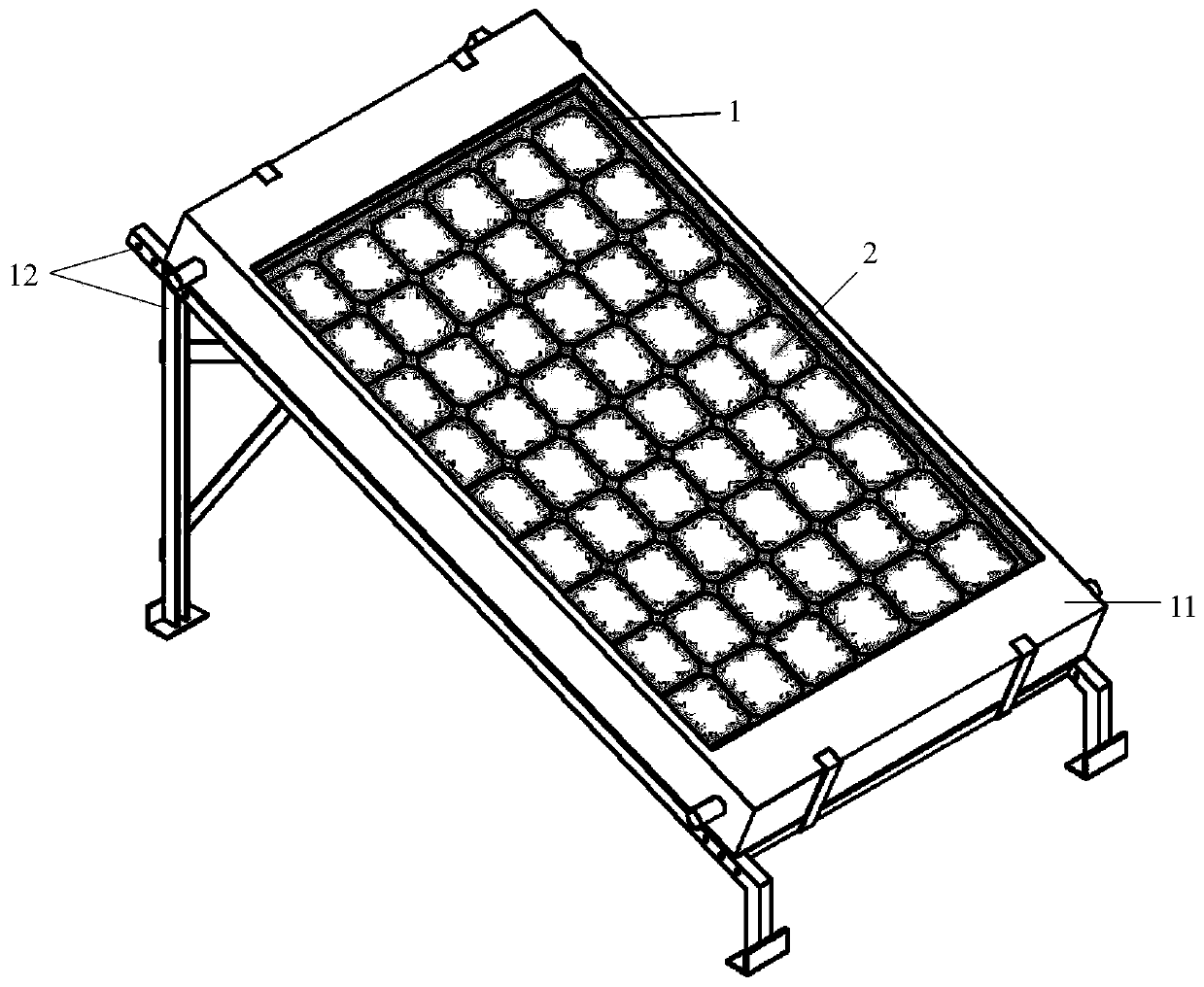
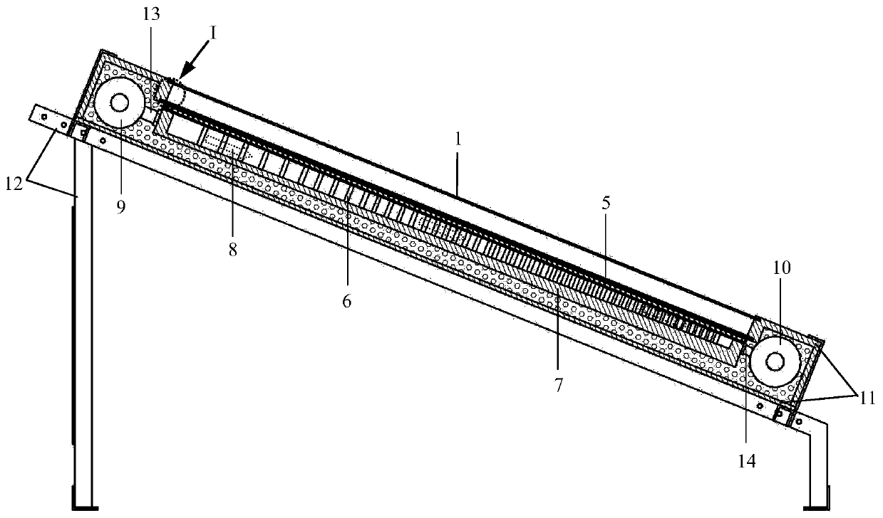
[0024] Such as Figure 1-5 As shown, a solar photovoltaic photothermal heat collection device includes a glass cover plate 1, a solar panel 2, an adhesive film layer 3, an insulating layer 4, a cover plate 5, micro-rib groups 6, a bottom plate 7, and a cold fluid header 9 , Thermal fluid header 10, thermal insulation shell 11, bracket 12, fluid inlet pipe 13, fluid outlet pipe 14.

[0025] Such as Figure 1-5 As shown, a solar photovoltaic photothermal heat collection device, a glass cover plate 1, a solar panel 2, and a heat collector plate 16 with a variable cross-section flow channel are fixed on the said heat collector along the light-facing side to the backlight side. Inside the thermal insulation shell 11; the variable cross-section flow channel heat collector plate 16 is formed by etching the bottom plate 7 of a plurality of parallel variable cross-section fluid ch...


PUM

PropertyMeasurementUnit
diameteraaaaaaaaaa
thicknessaaaaaaaaaa

Abstract

A solar photovoltaic photothermal heat collection device, which belongs to the technical field of solar photovoltaic equipment, is composed of a glass cover plate, a solar battery panel, a multifunctional adhesive layer, a variable cross-section flow channel heat collection plate, cold and hot fluid headers, and an insulation shell , the solar cell panel and the variable cross-section flow channel heat collector are laminated and connected by a multifunctional adhesive layer. The variable cross-section flow channel heat collector plate contains a number of parallel variable cross-section fluid channels. Micro-rib groups with surface density gradient changes are arranged in the variable cross-section fluid channels. The cold and hot fluid headers are placed at both ends of the inner space of the thermal insulation shell. The fluid inlet and outlet pipes are respectively connected with the variable cross-section flow channel heat collector plate; this device realizes uniform heat transfer and enhanced heat transfer in the flow direction of the working fluid; The effect of increasing flow resistance; the modified synthetic rubber film improves the heat transfer performance and operational reliability of the device.

Description

technical field [0001] The invention belongs to the technical field of solar photovoltaic equipment, and relates to a solar photovoltaic photothermal heat collection device, in particular to a solar photovoltaic photothermal heat collection device used in a comprehensive utilization system of solar light energy and thermal energy. Background technique [0002] Solar energy is an environmentally friendly renewable energy, which makes solar photovoltaic power generation widely used in the world. However, ordinary photovoltaic cells can only convert 4% to 17% of solar radiation energy into electrical energy. After deducting the reflection part, more than 50% of solar energy is converted into heat energy, and the photoelectric conversion efficiency is low; at the same time, the heat released by photovoltaic cells It directly leads to the continuous increase of its working temperature, which can reach as high as more than 80 degrees Celsius. Studies have shown that the increase ...

Claims


Application Information

Patent Timeline
Patent Type & Authority Patents(China)
IPC IPC(8): F24S20/25F24S70/20F24S80/30
CPCY02E10/40
Inventor 陈永平陈莹莹刘向东徐路遥
Owner YANGZHOU UNIV
Why Eureka
Try Eureka