
Electric heating film heater and method for assembling the heater

An electric heating film and heater technology, which is applied in the field of household appliances, can solve the problems of easily damaged electric heating film, waste of materials, slow assembly efficiency of electric heating film heaters, etc., so as to improve the efficiency of assembly and wiring, reduce the difficulty of installation, and reduce the installation cost. effect of difficulty

Pending Publication Date: 2018-11-27
GREE ELECTRIC APPLIANCES INC
View PDF7 Cites 3 Cited by
  • Summary
  • Abstract
  • Description
  • Claims
  • Application Information

AI Technical Summary

Problems solved by technology

[0005] Therefore, the technical problem to be solved by the present invention is that the electrothermal film heater in the prior art is easy to damage the electrothermal film during the installation process, resulting in waste of materials and slow assembly efficiency of the electrothermal film heater.

Method used


Image

  • Electric heating film heater and method for assembling the heater
  • Electric heating film heater and method for assembling the heater
  • Electric heating film heater and method for assembling the heater

Examples


Embodiment 1

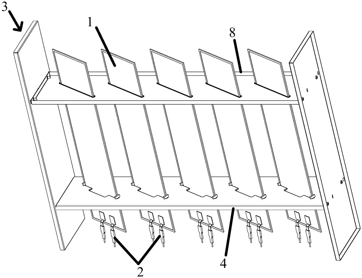
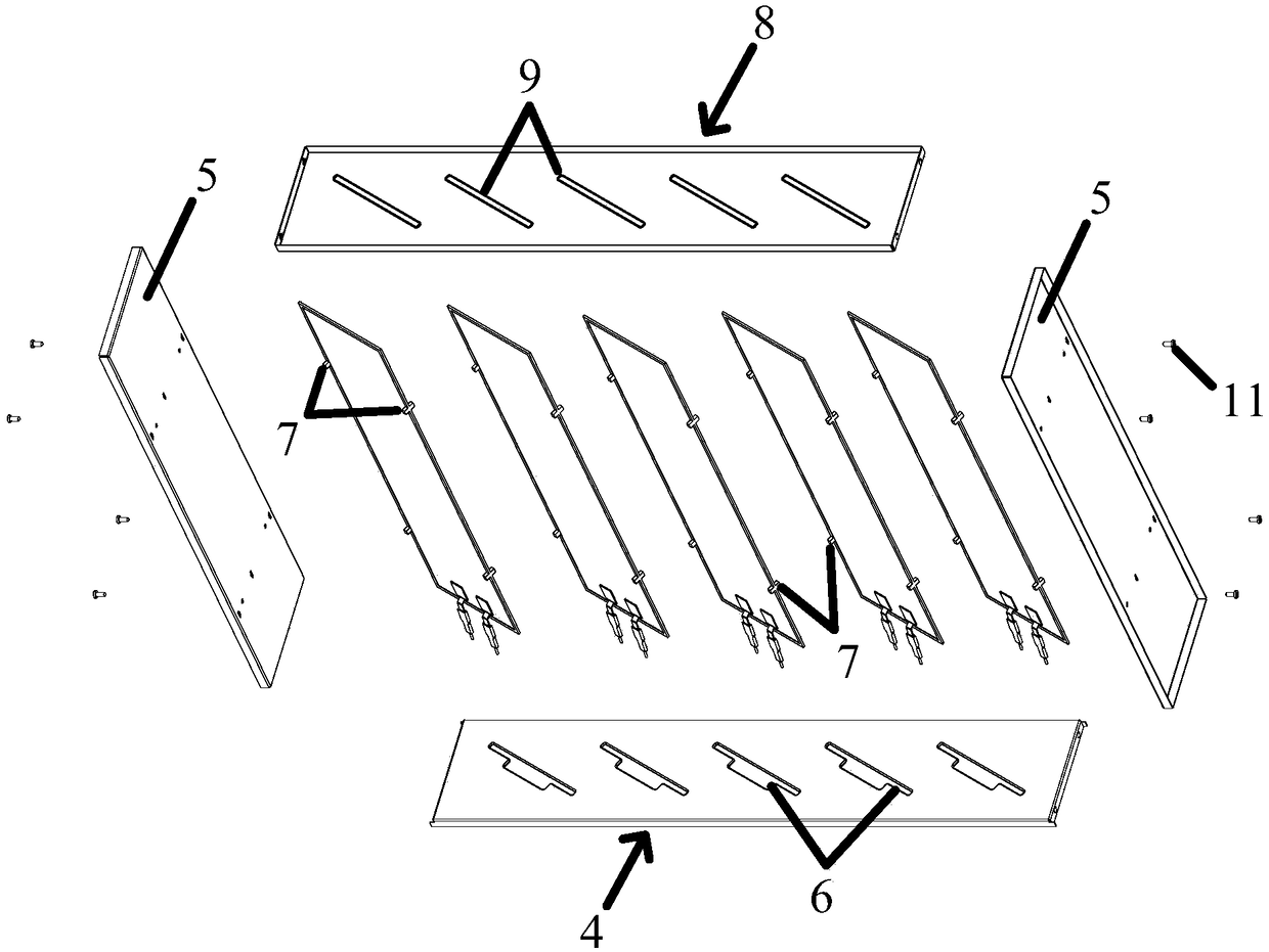
[0052] This embodiment provides an electric heating film heater, such as figure 1 and figure 2 shown, which includes

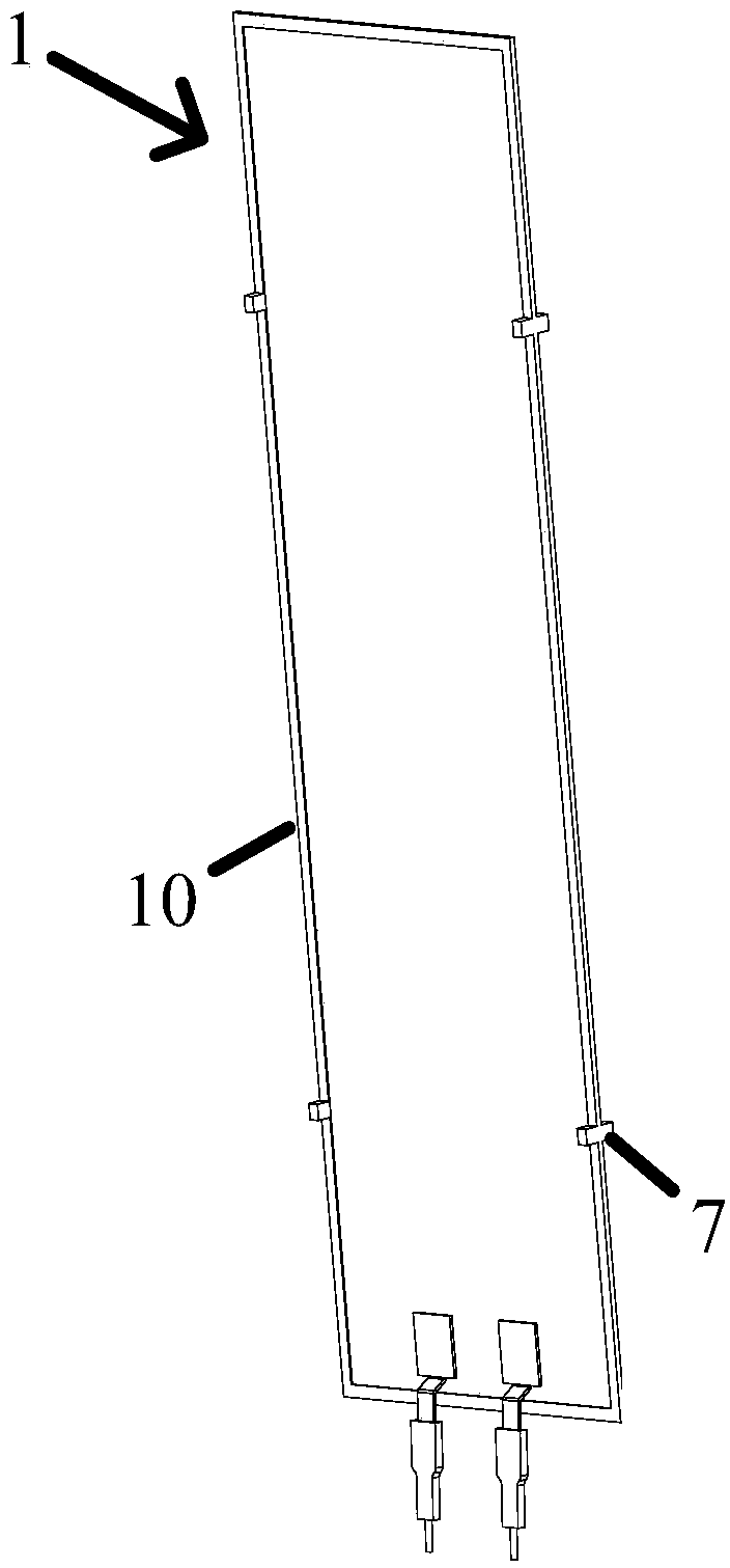
[0053] Electrothermal diaphragm 1, such as image 3 As shown, the lower end of the electrothermal diaphragm 1 is provided with a connecting terminal 2, and there are two connecting terminals 2 on each of the electrothermal diaphragm 1, and the two sides of the electrothermal diaphragm 1 are respectively provided with Two groups of protruding parts 7, the protruding parts 7 are arranged on the protective cover 10 of the outer contour edge of the electrothermal film 1;

[0054] Fixture 3, such as Figure 4 As shown, it includes a first clamping beam 4 connected to the lower side of the electrothermal diaphragm 1, a second clamping beam 8 connected to the upper side of the electrothermal diaphragm 1, and a first clamping beam 8 connected to the first clamping beam respectively. The beam 4 and the second clamping beam 8 are clamped and connected to support th...

Embodiment 2

[0067] The difference between this embodiment and Embodiment 1 is that the fixed frame 3 has only one first clamping beam 4, specifically, the fixed frame 3 includes a first clamping beam that is clamped and connected to the lower side of the electrothermal diaphragm 1 4 and a supporting plate respectively connected to the first clamping beam 4 for supporting the electrothermal diaphragm 1, and the first clamping beam 4 is provided with the lower end of the electrothermal diaphragm 1 and the connecting terminal 2 through the convex-shaped first slot 6, the protruding part 7 provided on the lower side of the electrothermal film 1 abuts against the upper surface of the first clamping beam 4, and the electrothermal film 1 vertical arrangement, the electrothermal diaphragm 1 is restricted from sliding out of the first clamping beam 4 through the protrusion 7 provided on the lower side of the electrothermal diaphragm 1 by the action of gravity. The fixing work of the electrothermal...


PUM


Abstract

The invention discloses an electric heating film heater, comprising an electric heating film sheet, wherein an end of the electric heating film sheet is provided with a wiring terminal; The fixing frame comprises a first clamping beam which is clamped and connected with the electric heating diaphragm and a support member which is connected with the first clamping beam for supporting the electric heating diaphragm, The first engagement beam is provided with a first slot adapted to one end portion of the electrothermal film, and the end portion of the electrothermal film is inserted into the first slot and is engaged with the first engagement beam. An insulating structure disposed between the electrothermal film and the first engagement beam and / or between the first engagement beam and the support member to prevent conduction between the electrothermal film and the support member. The invention solves the problems that the electric heating film is easily damaged in the installation process of the electric heating film of the electric heating film heater in the prior art, which leads to the waste of materials and the slow assembly efficiency of the electric heating film heater.

Description

technical field [0001] The invention relates to the technical field of household appliances, in particular to an electrothermal film heater and an assembly method of the heater. Background technique [0002] The electric heating film heater is a heating device that uses electricity as the energy source and resistance as the heating element to heat the room in the form of far-infrared heat. The electrothermal film heater itself has the advantages of long service life, small size, beautiful appearance, etc. without oxidation when heating, and is more and more widely used. The current electrothermal film heater usually includes a fixed frame and a number of electrothermal diaphragms installed on it. How to ensure the product reliability of the electrothermal film heater while improving the production efficiency of the heater, reducing the scrap rate and improving its product competitiveness is electric heating Research and development direction of membrane heater manufacturers...

Claims


Application Information

Patent Timeline
Patent Type & Authority Applications(China)
IPC IPC(8): F24D13/02F24D19/00
CPCF24D13/02F24D19/00F24D2200/08
Inventor 李忠正谢瑞良周小兵白相星廖泓斌张毅王红兵
Owner GREE ELECTRIC APPLIANCES INC
Learn More