
Liquid continuous-leakage preventing device

A liquid and shell technology, applied in the field of automatic control of liquid pipelines, can solve problems such as water leakage, corrosion consumption of enamel powder, corrosion of the inner tank, etc., to achieve the effect of high safety and reliability, easy installation, and prevention of continuous liquid leakage

Pending Publication Date: 2018-11-27
ARISTON THERMO CHINA
View PDF0 Cites 2 Cited by
  • Summary
  • Abstract
  • Description
  • Claims
  • Application Information

AI Technical Summary

Problems solved by technology

[0002] At present, water purifiers on the market generally use PP and other plastics as raw materials for pressure-bearing parts, such as filter bottles, etc. Once the pressure of tap water is too high, the upper limit of the pressure resistance of containers such as ultra-filtration bottles, filter bottles and other containers will burst, and the tap water pipeline will be damaged. If it is connected with the filter bottle and other containers, there will be continuous water leakage, causing unnecessary losses
[0003] In the water storage type electric water heater, although the surface of the electric water heater liner (water storage type electric water heater storage container) is treated with enamel, but in the long-term use process, due to the presence of a large number of ions in the tap water, the enamel will be damaged under the action of electrochemical corrosion. The powder will be consumed by corrosion, thus corroding the liner
At the same time, the production process will also affect the life of the inner tank. For example, in the enamelling process, at the welding seam between the end cap and the cylinder body, when the enameling process is not well controlled and the enamel powder cannot completely cover the gap, the enamel powder will not be able to achieve its due effect. Seriously affect the service life of the liner
[0004] In summary, once the container bursts or leaks due to corrosion, the liquid will continue to flow out from the liquid inlet

Method used


Image

  • Liquid continuous-leakage preventing device
  • Liquid continuous-leakage preventing device

Examples


Embodiment Construction

[0023] The present invention will be further described below in conjunction with specific drawings and embodiments.

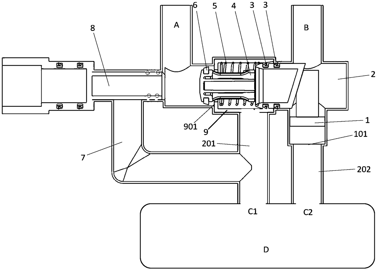
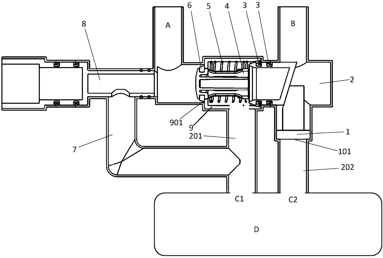
[0024] Such as figure 1 , figure 2 As shown, a device for preventing continuous leakage of liquid proposed by the present invention includes a slider 1, a housing 2, a first seal 3, a valve core 4, a return spring 5, a second seal 6, and a valve body 9;

[0025] The left end of the housing 2 is connected to a liquid inlet A, and the right end is connected to a liquid outlet B; a valve body 9 is provided in the middle of the housing 2; the valve body 9 is located between the liquid inlet A and the liquid outlet B;

[0026] The spool 4 is set in the valve body 9; the return spring 5 is sleeved on the spool 4, the left end of the return spring 5 is against the left end of the inner cavity of the valve body 9, and the right end of the return spring 5 is against the step on the spool 4 ;

[0027] The left end of the valve core 4 is provided with a second sealing...


PUM


Abstract

The invention provides a liquid continuous-leakage preventing device, comprising a slider, a casing, a first seal part, a valve spool, a reset spring, a second seal part and a valve body. The left endof the casing is connected with a liquid inlet end while the right end thereof is connected with a liquid outlet end; the valve body is arranged in the middle of the casing and disposed between the liquid inlet end and the liquid outlet end; the valve spool is arranged in the valve body and sleeved with the reset spring, and the left end of the reset spring is abutted against the left end of an inner cavity of the valve body while the right end thereof is abutted against a step on the valve spool; the second seal part is arranged at the left end of the valve spool, and disposed at the left side of the left seal surface of the valve body; the first seal part is arranged at the right end of the valve spool and disposed between the valve spool and the casing and / or valve body; the valve bodyis communicated with a first bypass pipe and the casing on the right side of the valve spool is communicated with a second bypass pipe; a bevel is arranged at the right end of the valve spool, the slider is arranged in the right end of the casing, one end of the slider fits the right end of the valve spool through the bevel. The device can automatically prevent continuous leakage of containers.

Description

technical field [0001] The invention relates to the field of automatic control of liquid pipelines, in particular to a device for preventing continuous leakage of liquid. Background technique [0002] At present, water purifiers on the market generally use PP and other plastics as raw materials for pressure-bearing parts, such as filter bottles, etc. Once the pressure of tap water is too high, the upper limit of the pressure resistance of containers such as ultra-filtration bottles, filter bottles and other containers will burst, and the tap water pipeline will be damaged. If it is connected to containers such as filter bottles, continuous water leakage will occur, causing unnecessary losses. [0003] In the water storage type electric water heater, although the surface of the electric water heater liner (water storage type electric water heater storage container) is treated with enamel, but in the long-term use process, due to the presence of a large number of ions in the t...

Claims


Application Information

Patent Timeline
IPC IPC(8): F16K31/143
CPCF16K31/143
Inventor 李洋甘超云张锋博袁正
Owner ARISTON THERMO CHINA
Learn More