
Corner connector

A technology of corner brackets and connectors, applied in the field of corner brackets, can solve problems such as deformation of door and window profiles, impact on service life, and complex corner bracket structures, and achieve the effects of uniform overall force, enhanced waterproof performance, and strong versatility

Inactive Publication Date: 2018-11-27
GUANGDONG EHE DOORS & WINDOWS TECH CO LTD
View PDF4 Cites 2 Cited by
  • Summary
  • Abstract
  • Description
  • Claims
  • Application Information

AI Technical Summary

Problems solved by technology

[0002] The existing corner brackets used at the corners of doors and windows, in order to strengthen the force and the fastness of the profile connection, many corner brackets use metal corner brackets, and the two ends of the corner brackets are respectively inserted into the two profiles for fixing, and bolts are used for fixing Fixed, and this kind of corner code structure is more complicated, inconvenient to install, easy to loose, poor firmness
[0003] There are also corner brackets for plastic parts. Many corner brackets directly fix the two ends and the profile through buckles, but the corner brackets are prone to tilt, which makes the force uneven, and the door and window profiles are deformed, which affects the service life.

Method used


Image

  • Corner connector
  • Corner connector
  • Corner connector

Examples


Embodiment Construction

[0023] The present invention will be described in further detail below in conjunction with the accompanying drawings.

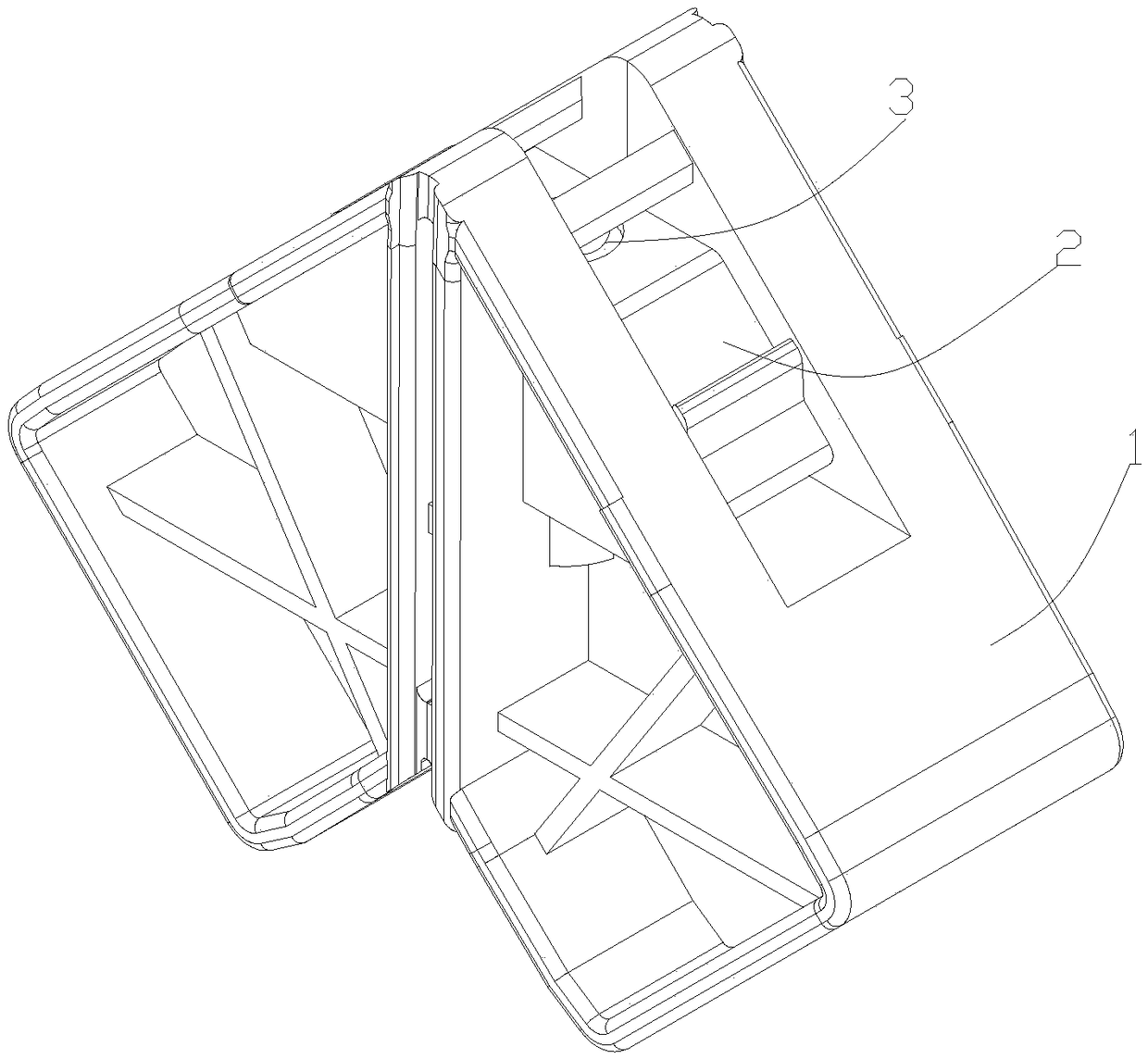
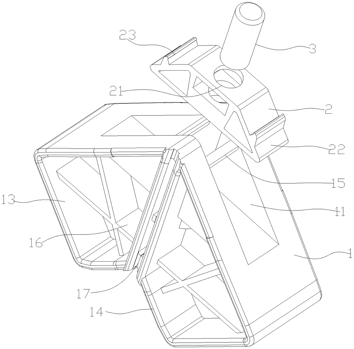
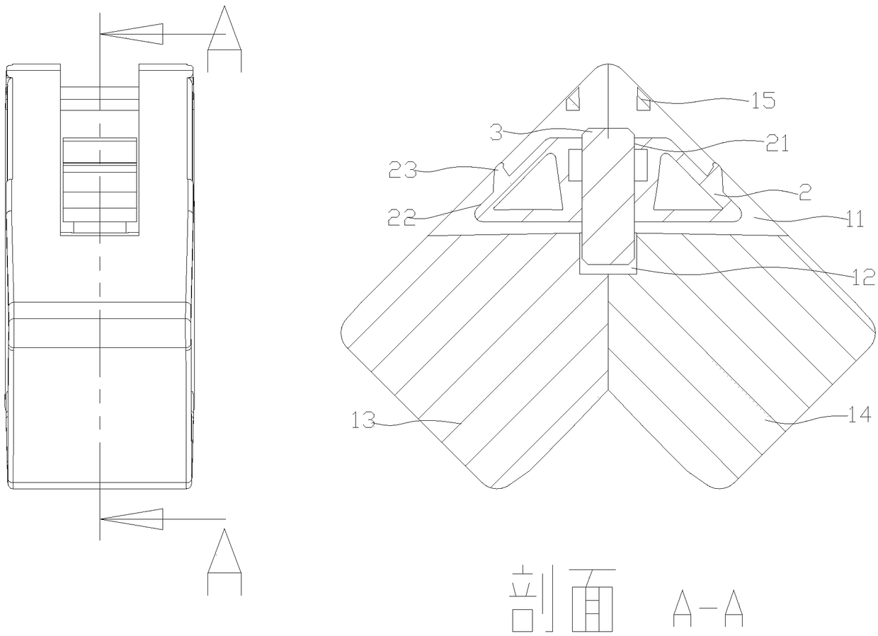
[0024] Figure 1-3 Schematically shows a corner code according to an embodiment of the present invention, including a first connecting piece 1, a second connecting piece 2 and a guide post 3, the cross section of the first connecting piece 1 is a “7” structure, the first connecting piece A chute 11 is provided at a corner of the member 1, and the second connecting member 2 is slidably mounted on the chute 11, and the bottom surface of the chute 11 and the bottom surface of the second connecting member 2 are arranged in parallel. The second connecting piece 2 is provided with a fixing hole 21 , and the chute 11 is provided with a guide groove 12 , the guide groove 12 is a circular groove, and its axis is perpendicular to the bottom surface of the chute 11 . The guide column 3 is fixedly arranged in the fixing hole 21, and the lower end of the guide column 3 i...


PUM


Abstract

The invention discloses a corner connector which comprises a first connecting piece, a second connecting piece and a guide pillar. A sliding chute is arranged in the first connecting piece, the secondconnecting piece is arranged in the sliding chute, a fixing hole is arranged in the second connecting piece, a guiding groove is arranged in the sliding chute, the guide pillar is arranged in the fixing hole and is fittingly connected with the guiding groove, and the axial direction of the guide pillar is identical to the direction of the sliding chute; the second connecting piece can slide in the sliding chute along the direction of the guide pillar. By the arrangement of the first connecting piece and the second connecting piece, matching with different profiles on two sides can be facilitated, connecting effect is achieved, and convenience in mounting and high universality are achieved; when an external force is applied to the second connecting piece, the second connecting piece can besqueezed to advance to the direction of the guiding groove so that the second connecting piece is always kept close fit with the first connecting piece, overall stress of the corner connector is uniform, and long service life is guaranteed.

Description

technical field [0001] The invention relates to the field of door and window installation accessories, in particular to a corner bracket. Background technique [0002] The existing corner brackets used at the corners of doors and windows, in order to strengthen the force and the fastness of the profile connection, many corner brackets use metal corner brackets, and the two ends of the corner brackets are respectively inserted into the two profiles for fixing, and bolts are used for fixing fixed, and this kind of corner code structure is relatively complicated, inconvenient to install, easy to loosen, and firmness is poor. [0003] There are also corner brackets for plastic parts. Many corner brackets directly fix the two ends and the profile through buckles, but the corner brackets are prone to inclination, which makes the force uneven, and the door and window profiles are deformed, which affects the service life. Contents of the invention [0004] According to one aspect...

Claims


Application Information

Patent Timeline
Patent Type & Authority Applications(China)
IPC IPC(8): E06B3/964E06B3/968
CPCE06B3/964E06B3/9681
Inventor 曾奎
Owner GUANGDONG EHE DOORS & WINDOWS TECH CO LTD
Learn More