High-frequency auxiliary converter for D-series high-speed train and control method thereof
A technology of high-frequency auxiliary and control methods, which is applied in the control/regulation system, the conversion of AC power input to DC power output, and the conversion of DC power input to DC power output, etc., which can solve the problems of heavy weight and large volume, and reduce the Effects of mass and volume, high power density, and efficiency improvement
- Summary
- Abstract
- Description
- Claims
- Application Information
AI Technical Summary
Problems solved by technology
Method used
Image
Examples
Embodiment 1
[0039] Embodiment 1, a high-frequency auxiliary converter for EMUs, the auxiliary power supply is a new type of high-frequency and high-power cascaded auxiliary power supply, because the soft switching technology and cascaded topology are adopted, the entire system is not sensitive to PWM Modulation and control algorithms are more demanding.
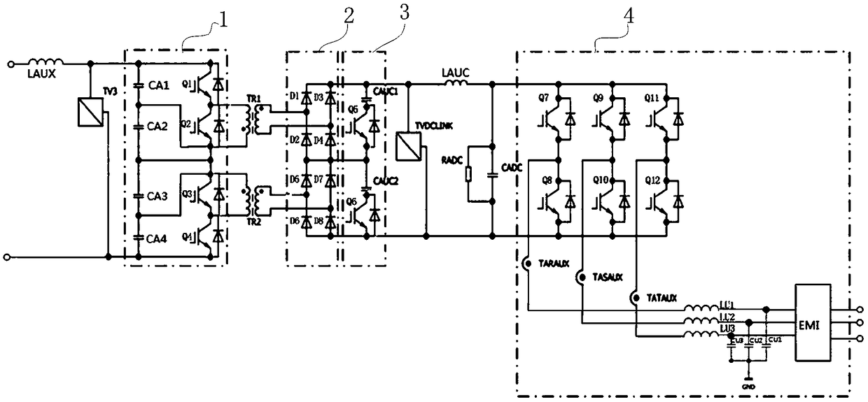
[0040] Such as figure 1As shown, it is the topology diagram of the main circuit used in the auxiliary converter, including series DC / DC chopper circuit 1 (including input filter circuit), series rectification circuit 2, resonant circuit 3, three-phase inverter circuit 4 ;The series DC / DC chopper circuit includes the input reactor LAUX, the filter capacitors CA1, CA2, CA3 and CA4 connected in series with it, and 4 chopping IGBTs (insulated gate bipolar transistors), namely Q1, Q2, Q3 and Q4; the function of the input filter circuit is to filter out the harmonics brought by the grid line voltage, and also to suppress the harmonic influenc...
Embodiment 2
[0043] Embodiment 2. The purpose of the resonant circuit is to realize the zero-current shutdown of the chopper IGBT. The key design is to determine the PWM control of the resonant IGBT. This embodiment is based on the high-frequency auxiliary converter of the EMU described in Embodiment 1. , a corresponding control method is proposed, including the following steps:
[0044] Step A, start the high-frequency auxiliary converter of the EMU, and precharge the capacitors CA1-CA4;
[0045] Step B. After the charging is completed (voltage sensor TV3 detects its voltage value), drive pulses are sent to the chopper IGBT and the resonant IGBT at the same time. The chopper IGBT includes Q1-Q4, and the resonant IGBT includes Q5 and Q6. During the drive pulse process, Including the following control process: the driving pulse width is very narrow in the initial stage;
[0046] (1) PWM phase control of the chopping IGBT and the PWM of the resonant IGBT: the driving pulse of the chopping I...
PUM
 Abstract
Description
Claims
Application Information
 - Generate Ideas
- Intellectual Property
- Life Sciences
- Materials
- Tech Scout
- Unparalleled Data Quality
- Higher Quality Content
- 60% Fewer Hallucinations
Browse by: Latest US Patents, China's latest patents, Technical Efficacy Thesaurus, Application Domain, Technology Topic, Popular Technical Reports.
© 2025 PatSnap. All rights reserved.Legal|Privacy policy|Modern Slavery Act Transparency Statement|Sitemap|About US| Contact US: help@patsnap.com


