
Loop compensation system based on zero-pole tracking mechanism

A loop compensation, zero-pole technology, applied in control/regulation systems, output power conversion devices, DC power input conversion to DC power output, etc., can solve the problems of power switch tube area waste, design difficulty, loss increase, etc. , to ensure the effect of phase margin

Active Publication Date: 2018-11-23
GUANGZHOU UNIVERSITY
View PDF2 Cites 1 Cited by
  • Summary
  • Abstract
  • Description
  • Claims
  • Application Information

AI Technical Summary

Problems solved by technology

However, the disadvantage of the BOOST converter is that there is a left-half plane zero point in its voltage loop, which brings challenges to the loop compensation of the technology.
For example, a new type of three-state topology, which can completely eliminate the existence of the left zero point, but the additional power switch tube brings about a waste of area and an increase in loss; in addition, the existing technology uses low-frequency control technology, Adaptive voltage positioning technology and output voltage leading edge modulation method to reduce the adverse effects caused by the left zero point, but these methods either lead to excessive output ripple or difficult to control the working sequence, which brings a certain degree of difficulty to the design

Method used


Image

  • Loop compensation system based on zero-pole tracking mechanism
  • Loop compensation system based on zero-pole tracking mechanism
  • Loop compensation system based on zero-pole tracking mechanism

Examples


Embodiment Construction

[0020] The following will clearly and completely describe the technical solutions in the embodiments of the present invention with reference to the accompanying drawings in the embodiments of the present invention. Obviously, the described embodiments are only some, not all, embodiments of the present invention. Based on the embodiments of the present invention, all other embodiments obtained by persons of ordinary skill in the art without creative efforts fall within the protection scope of the present invention.

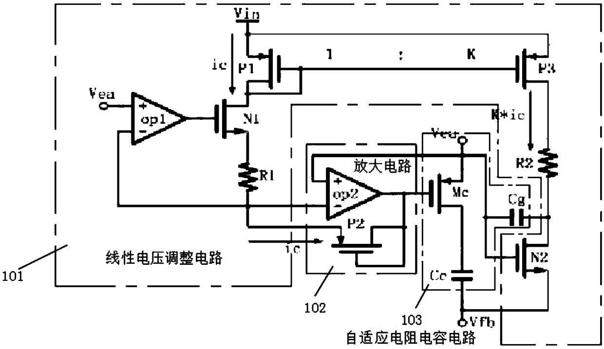
[0021] see figure 1 , is a schematic diagram of the principle of the loop compensation system based on the pole-zero tracking mechanism provided by the present invention. The loop compensation system includes a linear circuit voltage output terminal Vout, a load resistor Rfb1, a load resistor Rfb2, an operational amplifier AMP, a capacitor Cc, an adjustable resistor RMc, and an adjustable capacitor Cg.

[0022] The voltage output terminal Vout of the linear circui...


PUM


Abstract

The invention discloses a loop compensation system based on a zero-pole tracking mechanism, comprising a linear voltage adjustment circuit, an amplifying circuit and an adaptive resistor-capacitor circuit, one end of the linear voltage adjustment circuit is connected with the amplifying circuit, and the other end of the linear voltage adjustment circuit is connected with the adaptive resistor-capacitor circuit; an input current, connected from the linear voltage adjustment circuit, of the amplifying circuit is a first input current, and an input current, connected from the linear voltage adjustment circuit, of the amplifying circuit is a second input current; and the adaptive resistor-capacitor circuit regulates a ratio of the first input circuit to the second input circuit according to adjustment parameters input by virtue of the linear voltage adjustment circuit, so as to realize zero-pole tracking compensation.

Description

technical field [0001] The invention relates to the technical field of semiconductor integrated circuits, in particular to a full-load loop compensation system. Background technique [0002] With the rapid development of smart portable electronic devices, technology has higher and higher requirements for power management, which enables power supply chips to maintain efficient and stable operation in a multi-technical and complex environment. As for the DC-DC converter, because of its advantages such as high conversion efficiency and strong load capacity, it is the most widely used in power management ICs. In particular, BOOST converters are indispensable in power management solutions because of their special boost characteristics. indispensable position. However, the disadvantage of the BOOST converter is that there is a left-half plane zero point in its voltage loop, which brings challenges to the loop compensation of the technology. [0003] The prior art proposes some t...

Claims


Application Information

Patent Timeline
Patent Type & Authority Applications(China)
IPC IPC(8): H02M3/00
CPCH02M3/00H02M1/0003
Inventor 曾衍瀚王阳廖锦锐黄华杰
Owner GUANGZHOU UNIVERSITY
Learn More